Cisco Tetration - Hands-On Lab
Module08: Ingest Appliance - AWS VPC Flow Logs and ASA NAT Stitching
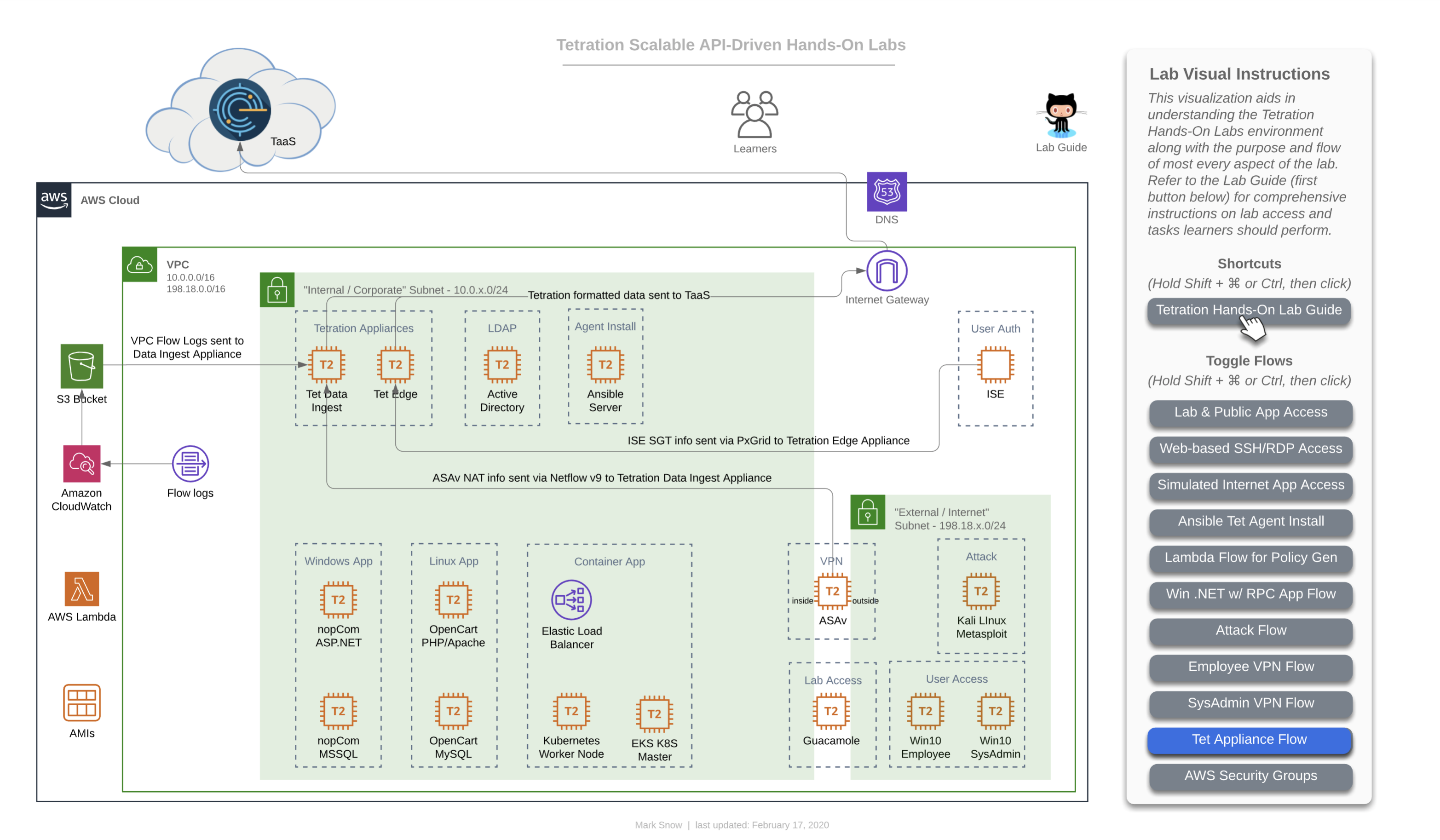
This diagram depicts the flow of traffic used by various devices to utimately ingest information into the Tetration cluster. The Tetration Edge appliance is used to subscribe to the pxGrid from ISE for SGT and user-based policy. The Tetration Data Ingest appliance is used to collect NetFlow v9 info from the ASAv which is useful in stitching together flows of traffic from outside the firewall all the way through being NAT’d by that ASAv and then traversing to the internal corporate network and making their way to app frontends. This same Tetration Data Ingest appliance is used to collect Flow Logs from an AWS VPC via an S3 bucket. This is useful for collecting traffic from any workload that may not have (or be able to have) a Tetration agent installed on it.
Steps for this Module
AWS VPC Flow Logs
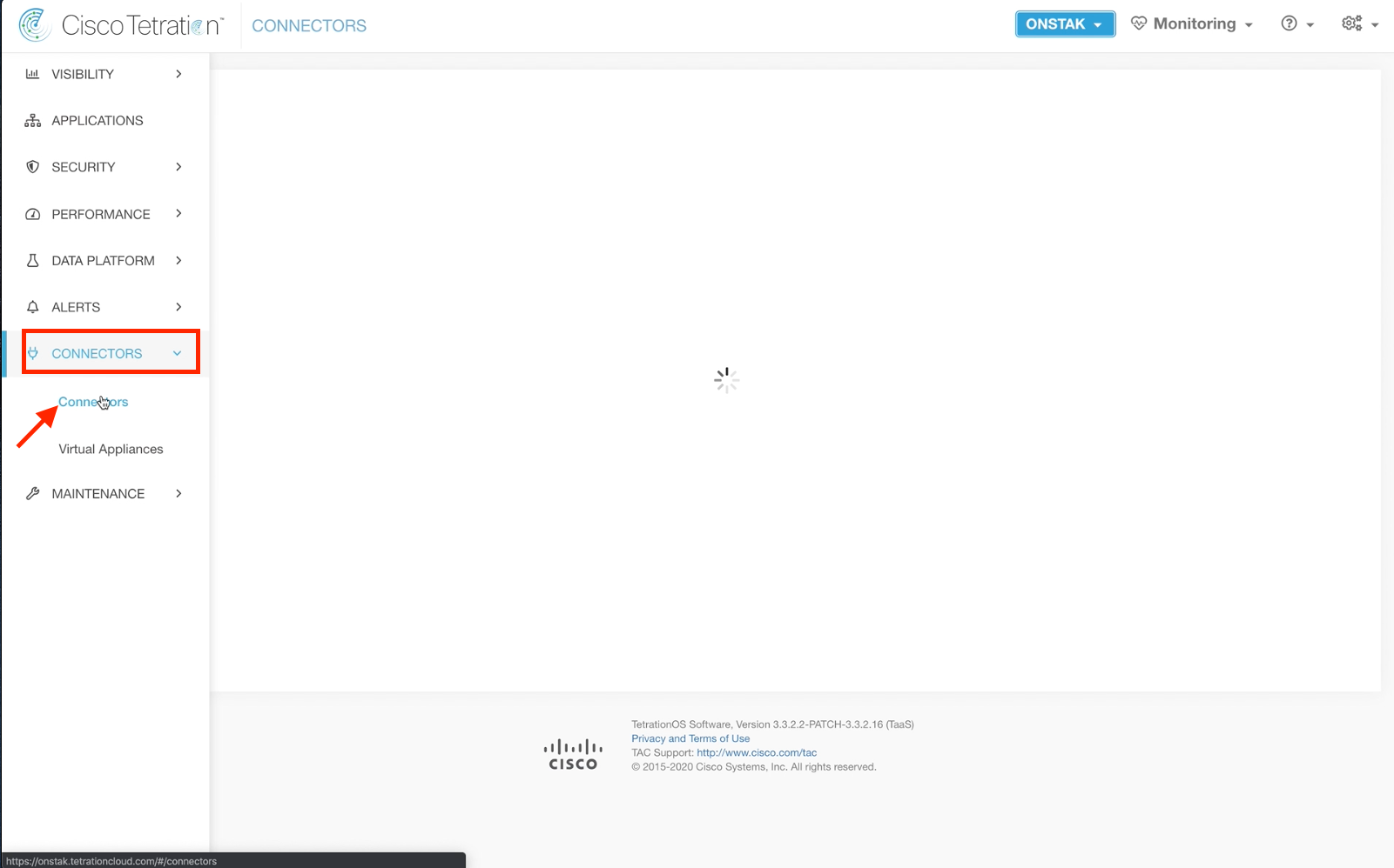
Step 001 - Naviaget to Connectors
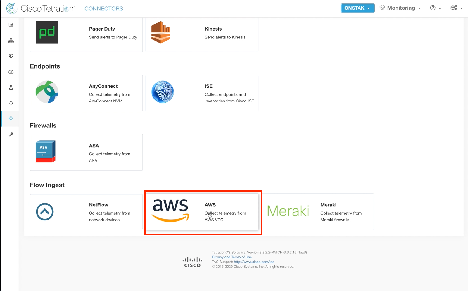
Step 002 - Select AWS under Flow Ingest
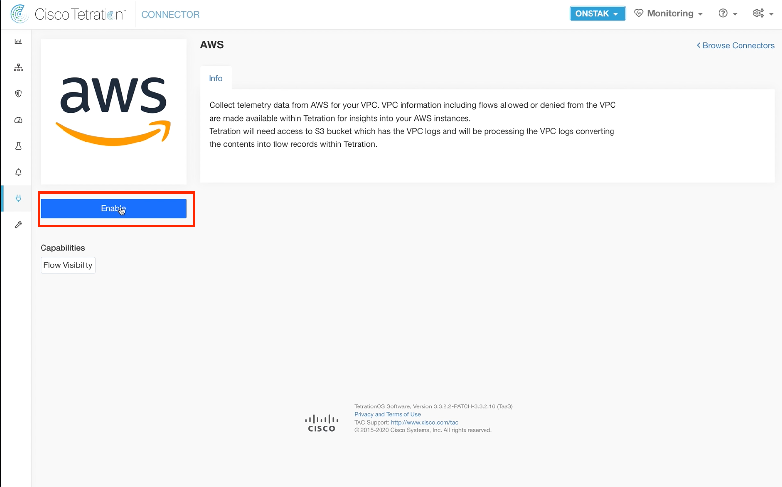
Step 003 - Enable the AWS Flow Ingest Connector
Step 004 - Deploy Appliance
Step 005 - Proceed to the next step
Step 006 - Enter the appliance details
Step 007 - Complete entering details
Step 008 - Download the .iso file
Step 009 - Save the file to disk
Step 010 - Open a session to the Tetration Data Ingest Appliance
Step 011 - Copy the files from the .iso to the appliance
Step 012 - Wait for all files to copy
Step 013 - Test connectivity and verify files
Step 014 - Reboot the appliance
Step 015 - Reconnect when the appliance finished rebooting
Step 016 - Copy the resolv.conf file to /etc/resolv.conf
Step 017 - Reboot the appliance again
Step 018 - Examine the logs
Step 019 - Proceed to the next step
Step 020 - Finish the Deploy Virtual Appliance wizard
Step 021 - Check status of the Ingest Appliance
Step 022 - Verify the VM details
Step 023 - Configure NTP
Step 024 - Verify and save NTP configuration
Step 025 - Configure Logs
Step 026 - Verify and save Log configuration
Step 027 - Enable a connector
Step 028 - Select the AWS connector
Step 029 - Check status of AWS connector
Step 030 - Check logs on the appliance
Step 031 - Verify AWS connector status
Step 032 - Begin AWS Configuration
Step 033 - Configure AWS details
Step 034 - Complete AWS configuration
Step 035 - Begin AWS log configuration
Step 036 - Verify and Save Configs
ASA Connector and NAT Stitching
Step 037 - Open a session to the Windows 10 employee desktop
Step 038 - Open a web browser and point to the NAT IP of the IIS web server
Step 039 - Navigate to Flow Search and filter the flows
Step 040 - Click on the graph
Step 041 - Review the flow without NAT information
Step 042 - Navigate to Virtual Appliances
Step 043 - Select Tetration Data Ingest
Step 044 - Enable another connector
Step 045 - Enable the ASA connector
Step 046 - Click on the ASA connector
Step 047 - Review the IP bindings
Step 048 - Open a session to the ASA
Step 049 - Review ASA configuration
Step 050 - Review ASA verification commands
Step 051 - Navigate to Flow Search
Step 052 - Click on time range and select 1hr
Step 053 - Filter the flows
Step 054 - View flow details
Step 055 - Review Related Flow information
AWS VPC Flow Logs
Navigate to Connectors.
Under Flow Ingest, select the AWS connector.
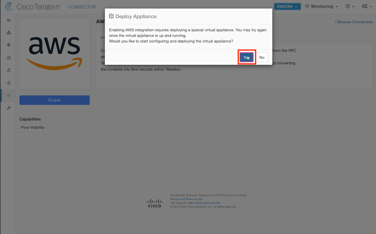
Click Enable to begin deploying the appliance.
Select Yes to begin deploying the appliance.
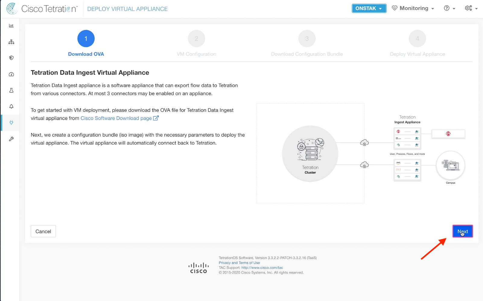
Although the instructions on screen indicate downloading an OVA file, this is not necessary because we have deployed the appliance already in AWS. Click Next to continue.
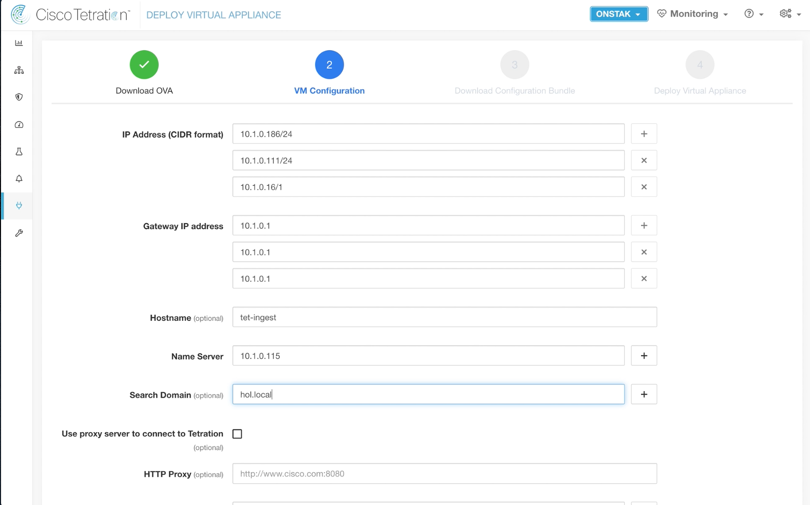
The below information will be used to create a .iso file that we will download, extract, and then copy the files to the appliance.
If we were deploying an on-prem appliance, then we would mount the .iso to the virtual CD-ROM on the VM.
Fill in the appropriate details as can be found on your student worksheet. There are three IP addresses for the appliance because it runs three Docker containers that must each have a routable IP address on the network. The IP address of the Active Directory server should be entered as the Name Server.
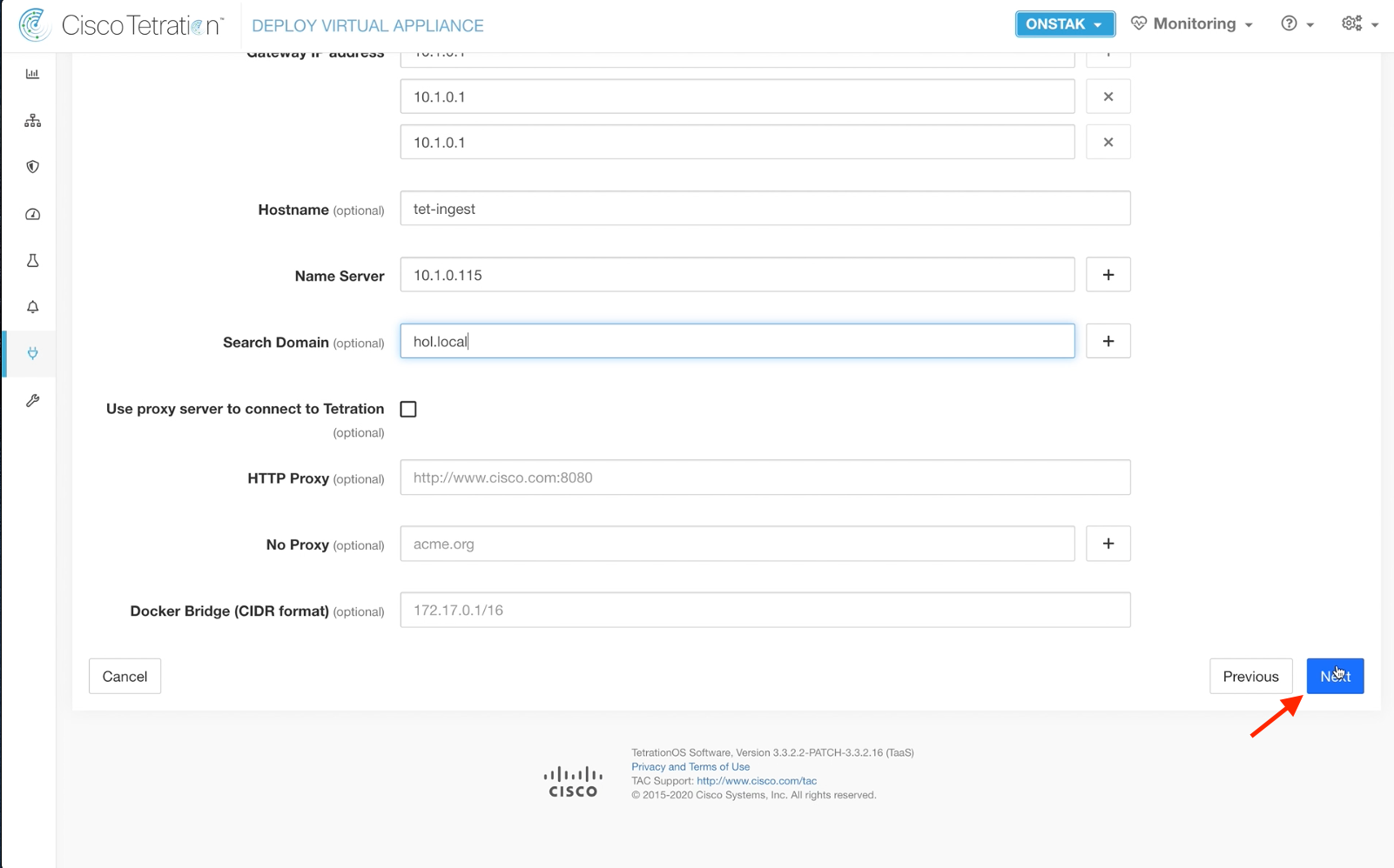
Scroll down and click Next to continue.
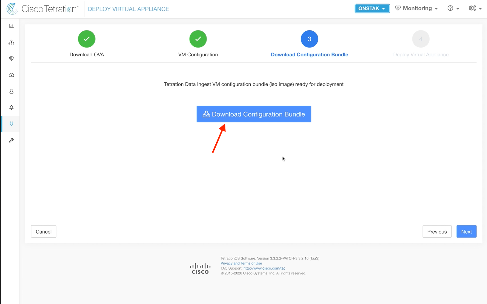
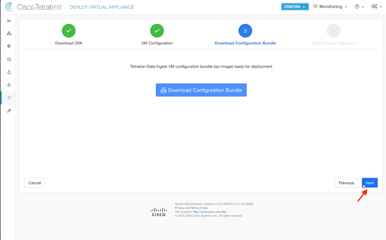
Click Download Configuration Bundle to download the .iso file to your desktop.
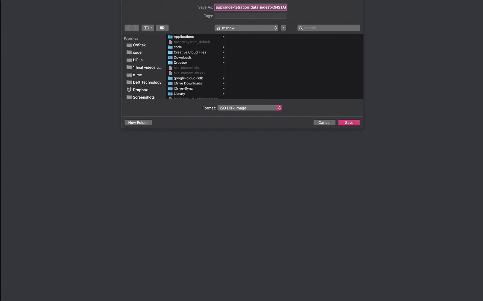
Save the .iso file to your desktop.
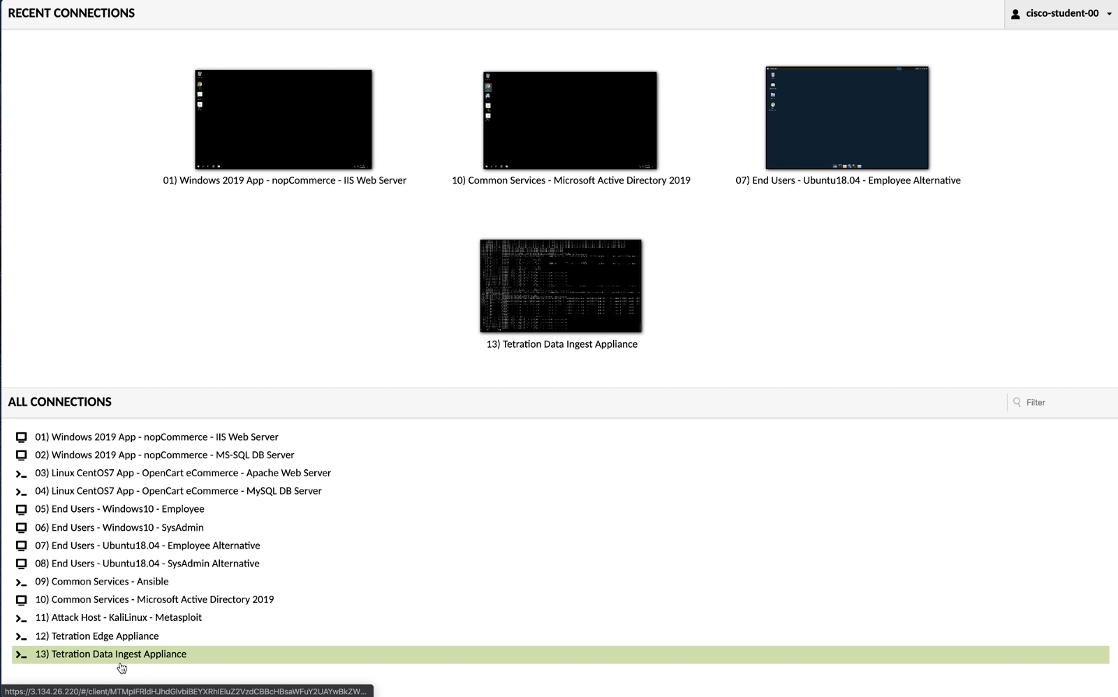
Open a session to the Tetration Data Ingest Appliance. This opens a session to the already deployed instance of the ingest appliance in AWS.
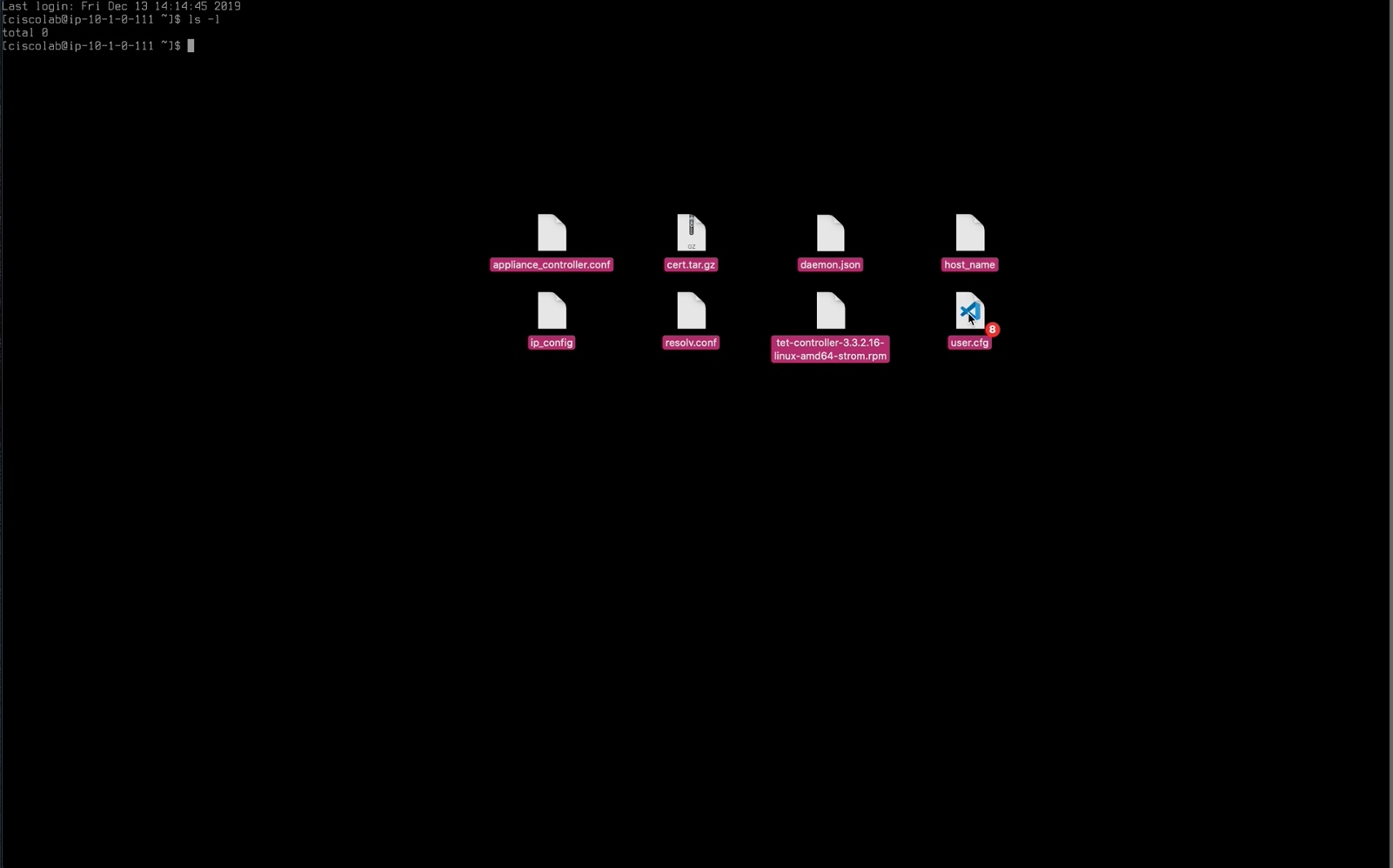
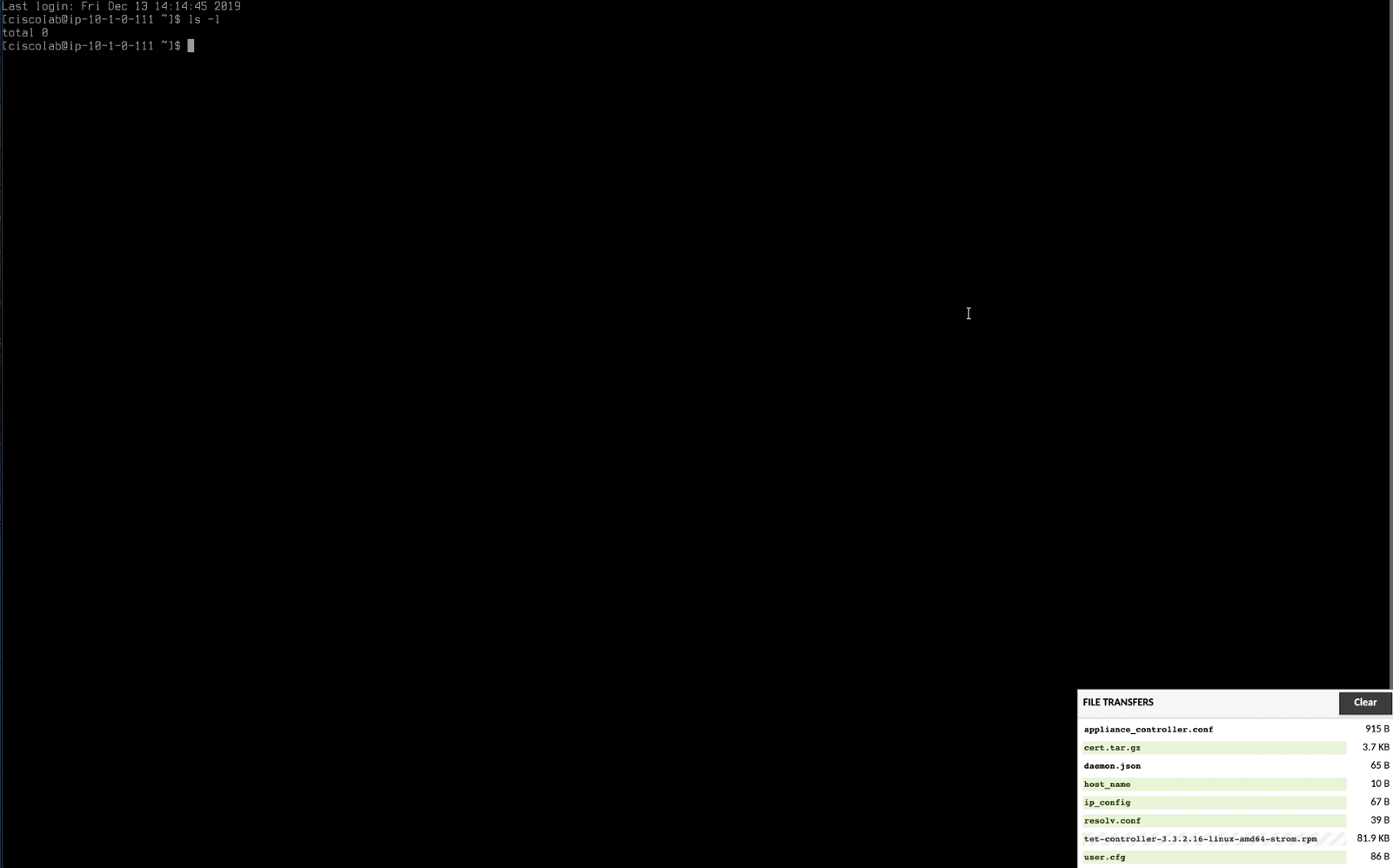
Extract the contents of the .iso file and drag the contents to the ingest appliance window that we opened in step 10.
Wait for all of the files to fully copy. A status window should be displayed in the lower right hand corner of the screen.
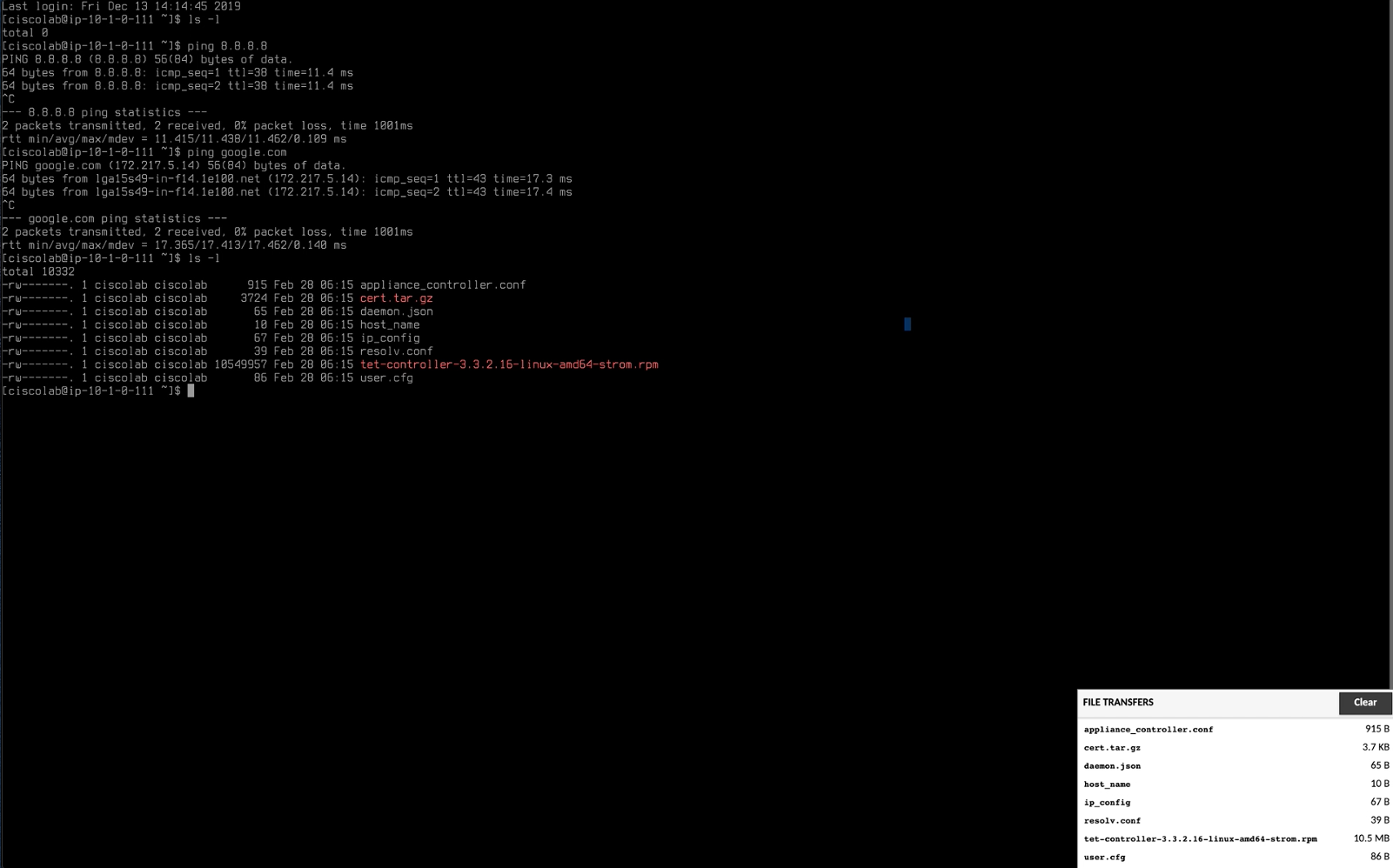
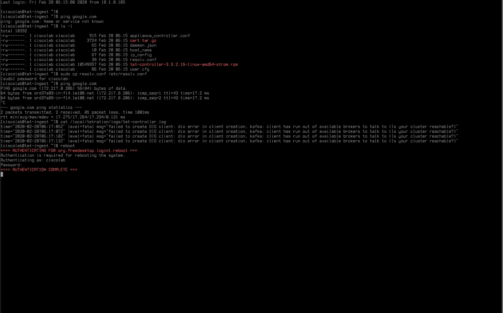
Make sure the appliance has outbound Internet connectivity by pinging well-known web sites such as google.com. Do an ls -l to make sure that the files we copied are present on the appliance.
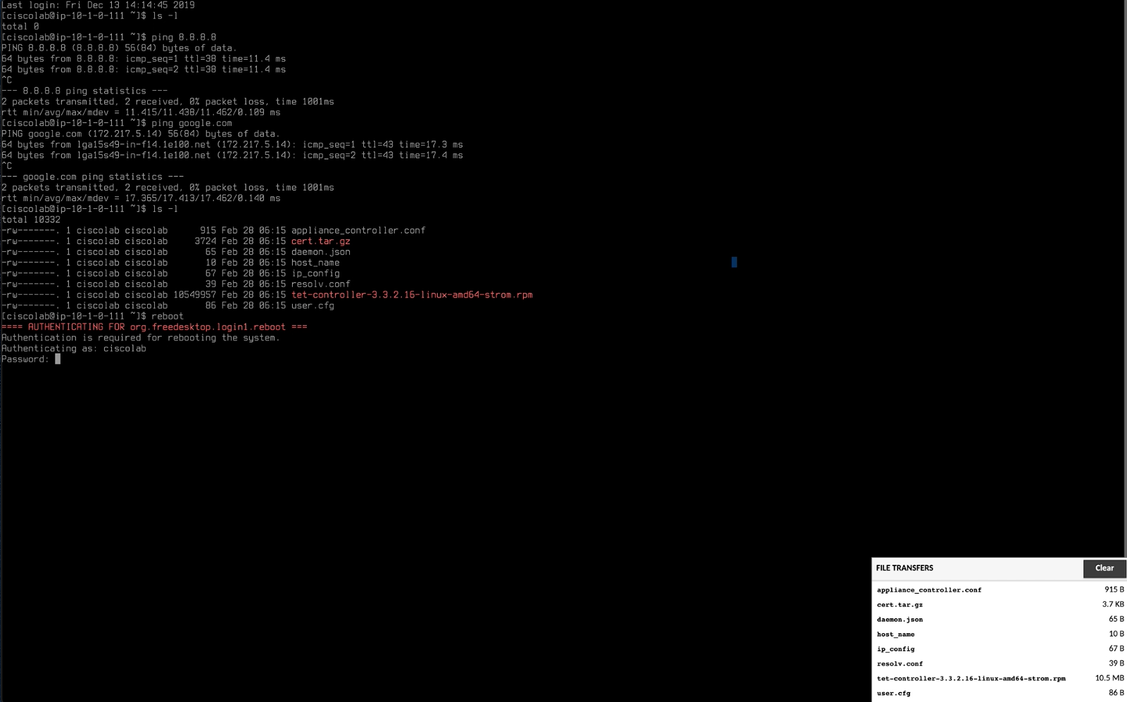
Type reboot to reboot the appliance.
Once the appliance is done rebooting, reconnect to the session.

Copy the resolv.conf file to /etc/resolv.conf. Use the command sudo cp resolf.conf /etc/resolv.conf.
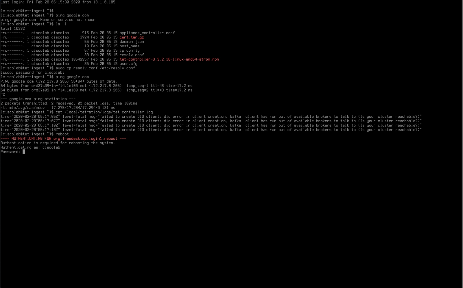
Type reboot to reboot the appliance again.
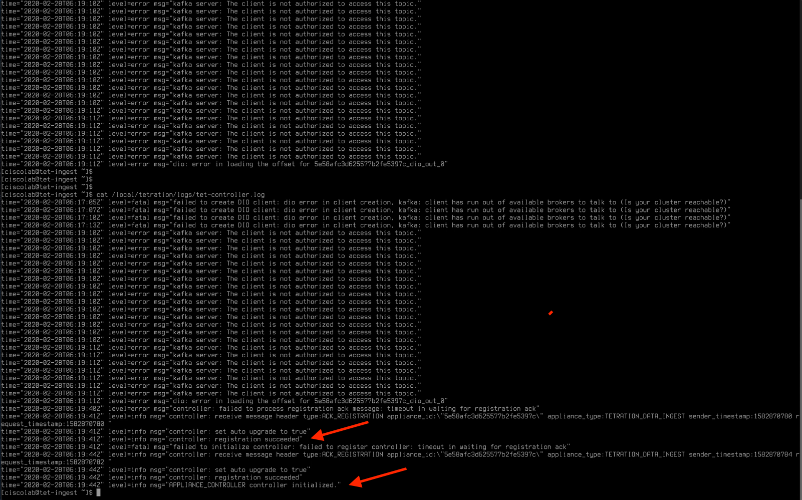
Reconnect to the appliance once it is done rebooting. Review the log files using the command cat /local/tetration/logs/tet-controller.log. You will at first see error messages as shown in the below image. Once the messages “registration succeeded” and “controller initialized” appear in the output, we are read to proceed with the next task.
Click Next in the Deploy Virtual Appliance wizard.
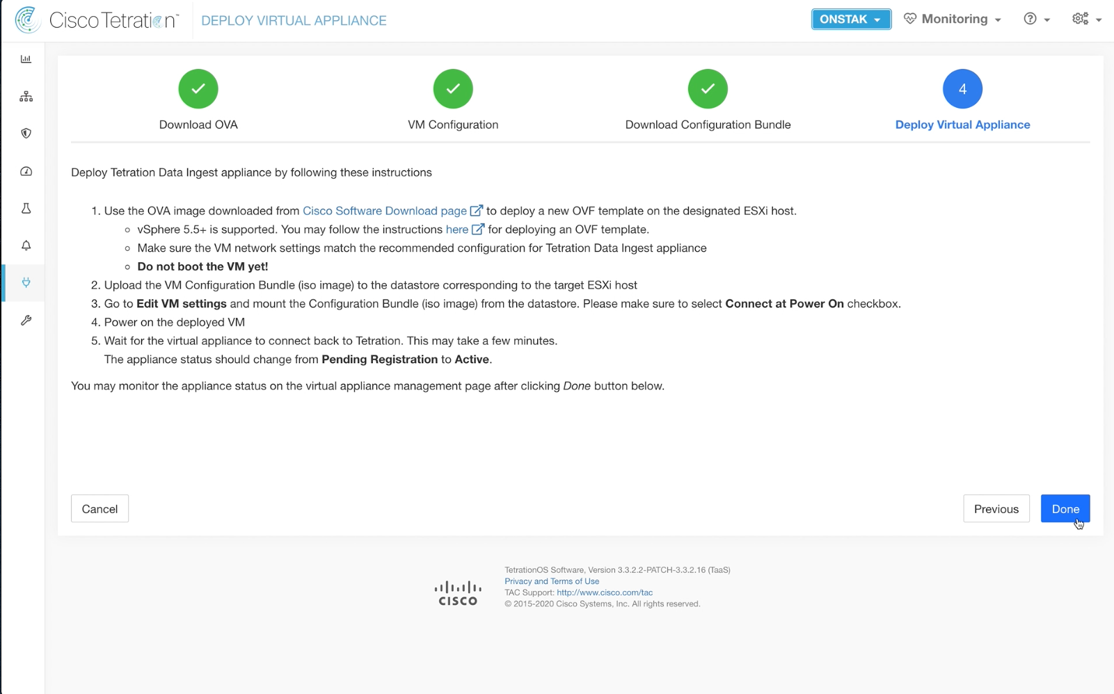
The instructions here once again refer to deployment of an on-prem appliance in VMware. Click Done to complete the wizard.
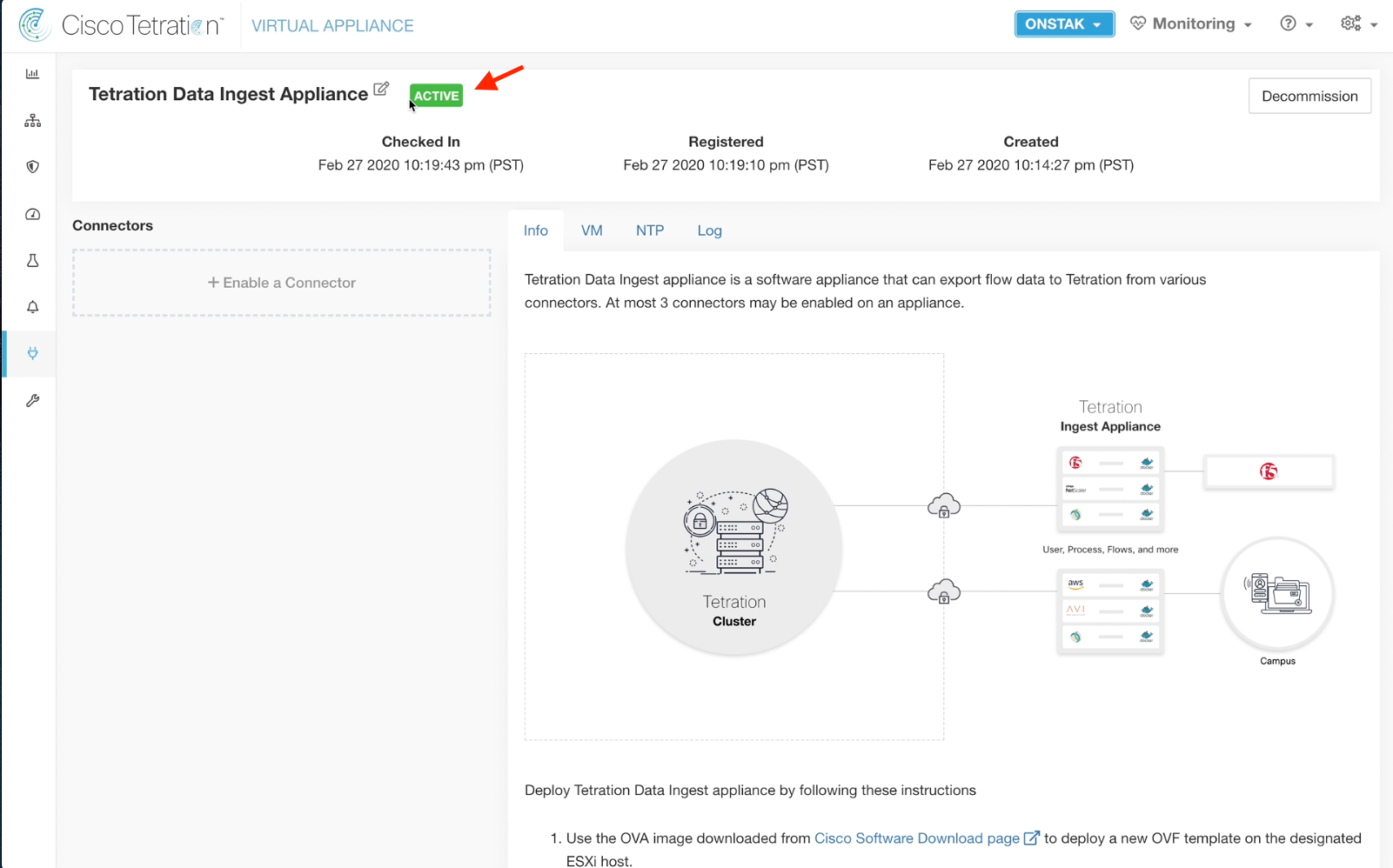
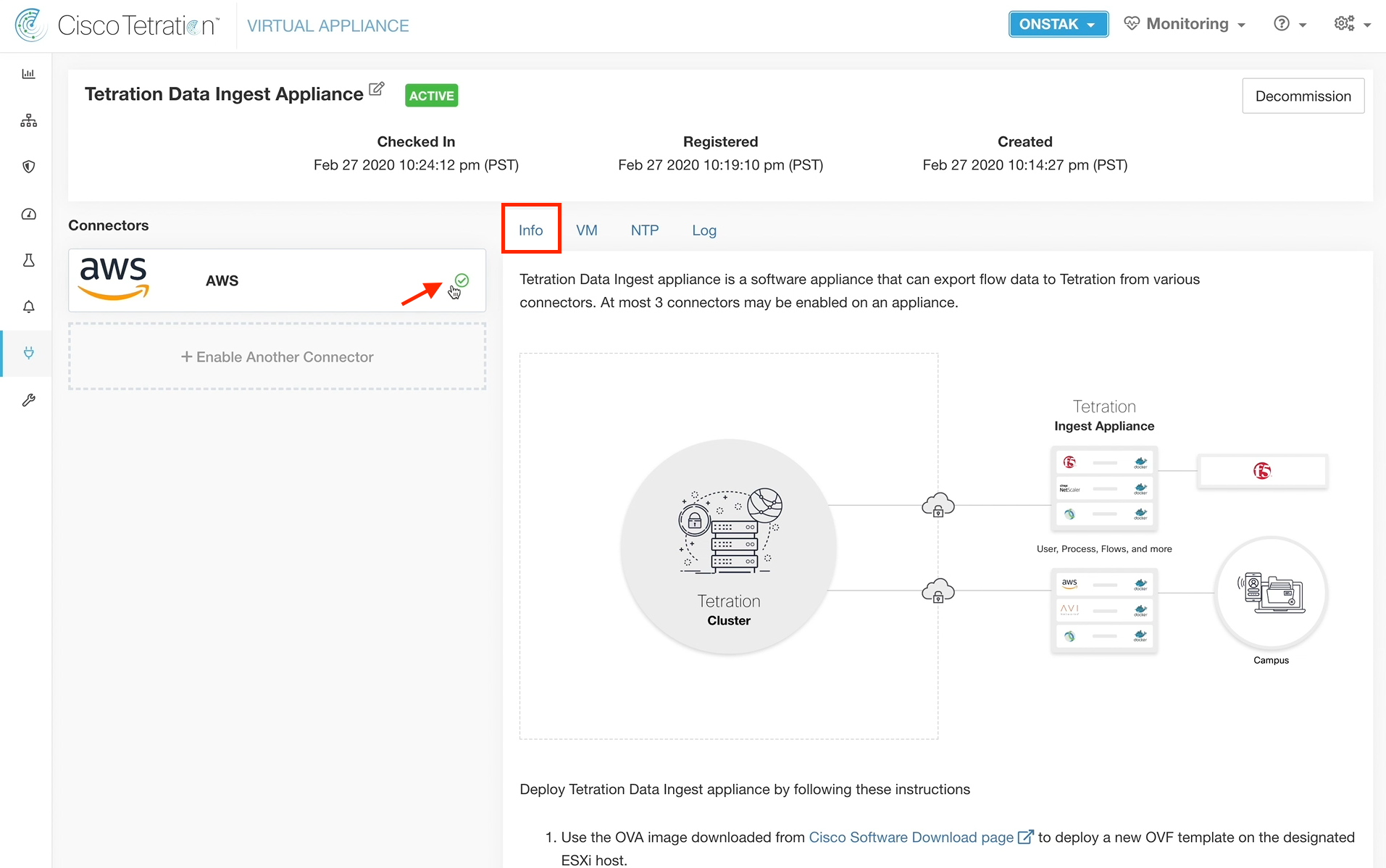
Check the status of the Data Ingest Appliance. It should be Active.
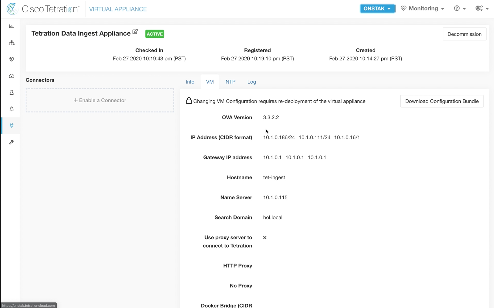
Click on the VM tab to review the configuration. The information that we entered and downloaded into the .iso file should be displayed.
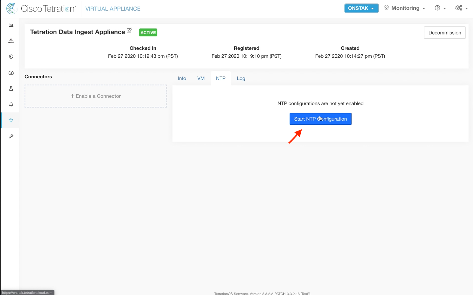
Click on the NTP tab and click Start NTP Configuration.
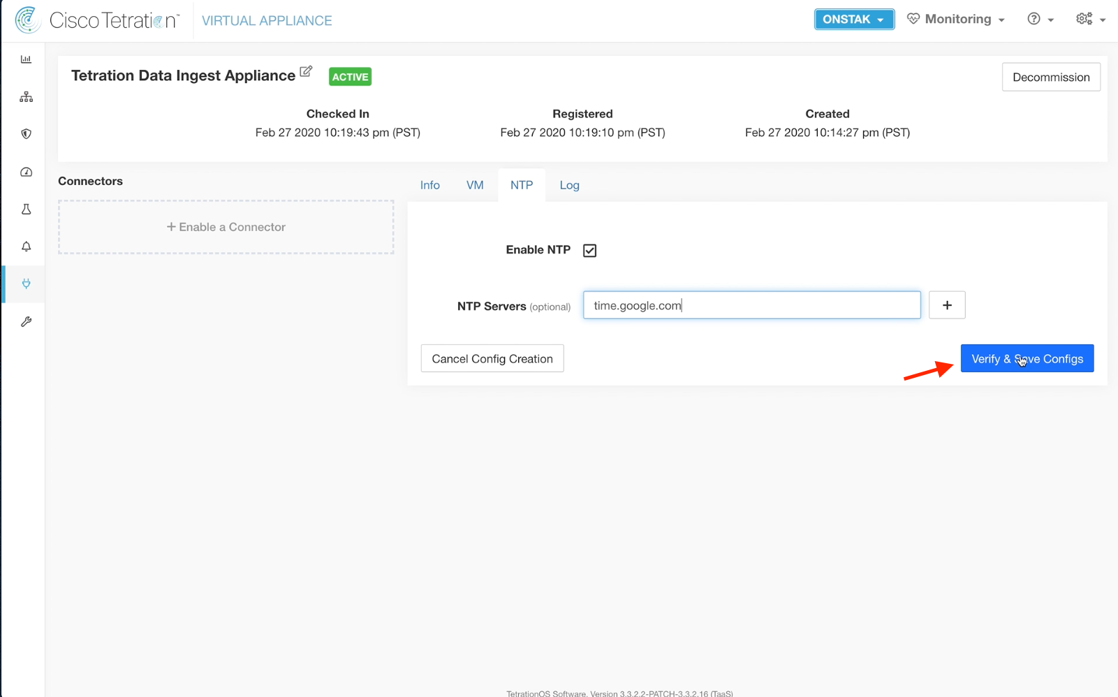
Enter the NTP server time.google.com and click Verify & Save Configs.
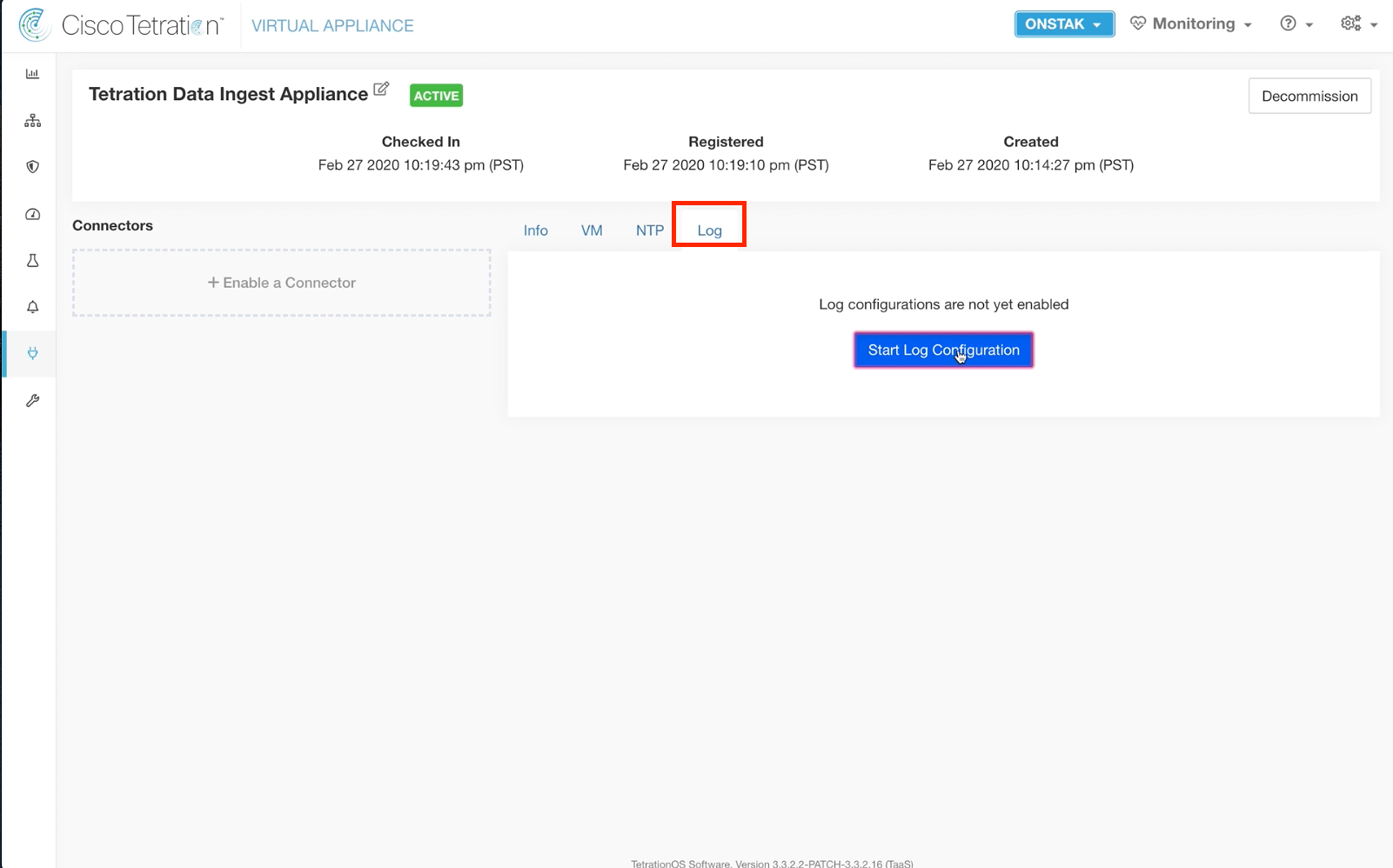
Click on the Log tab and select Start Log Configuration.
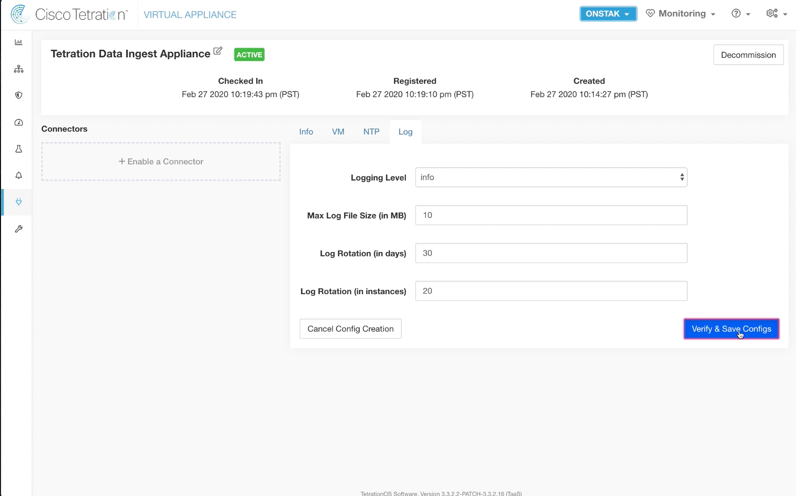
Change the Logging Level to info, and then click Verify & Save Configs.
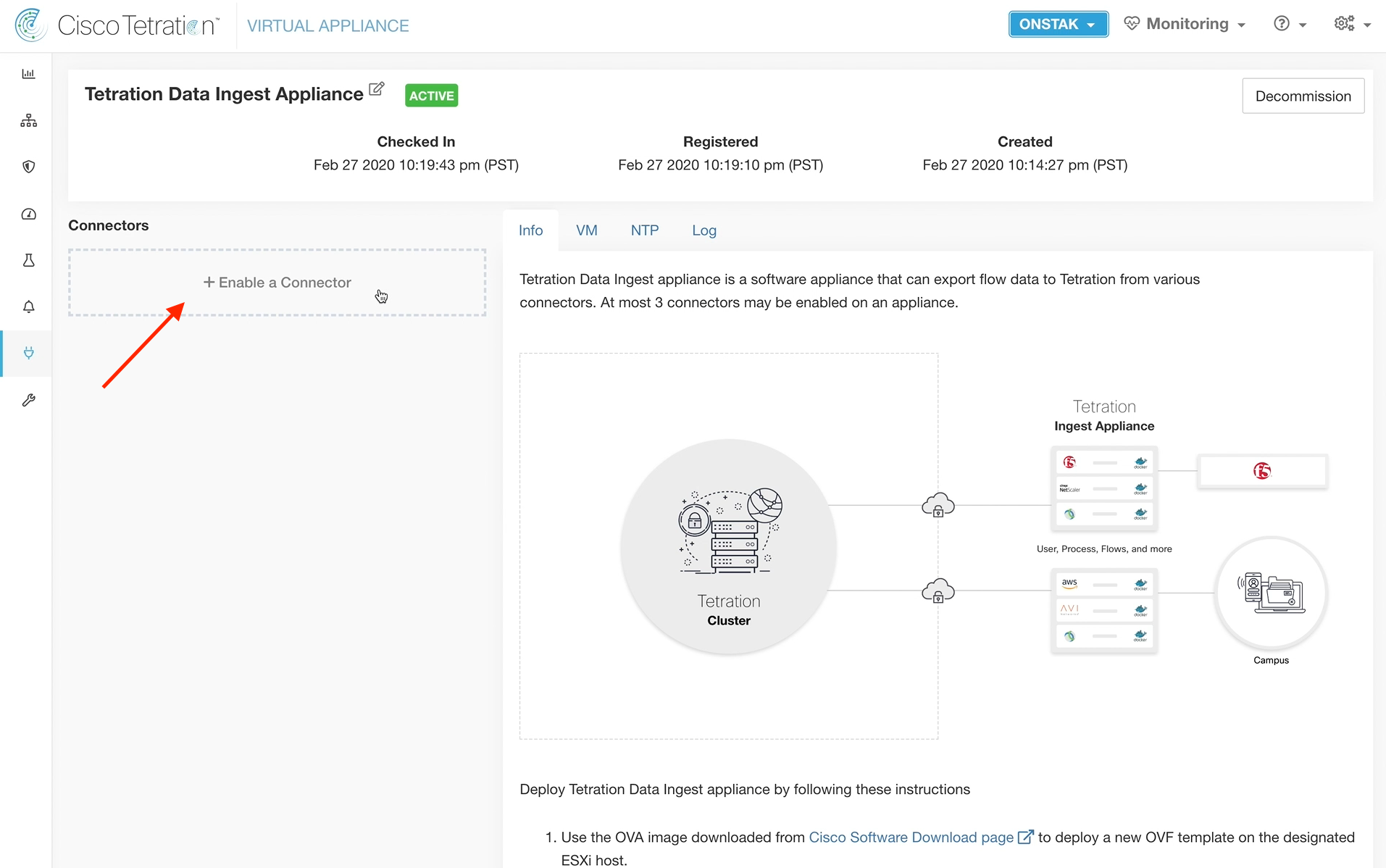
Click the button to Enable a Connector.
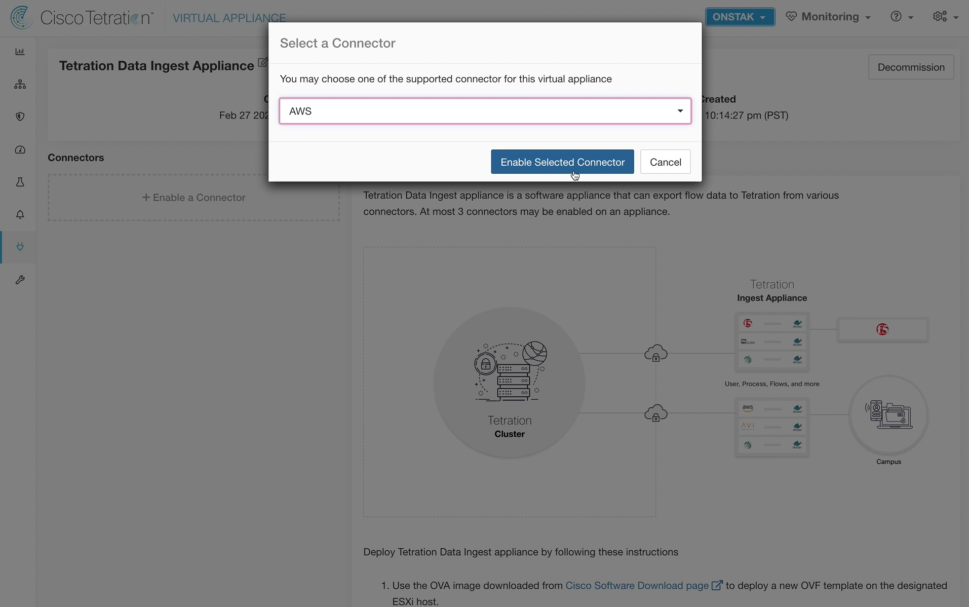
Choose AWS and enable the connector.
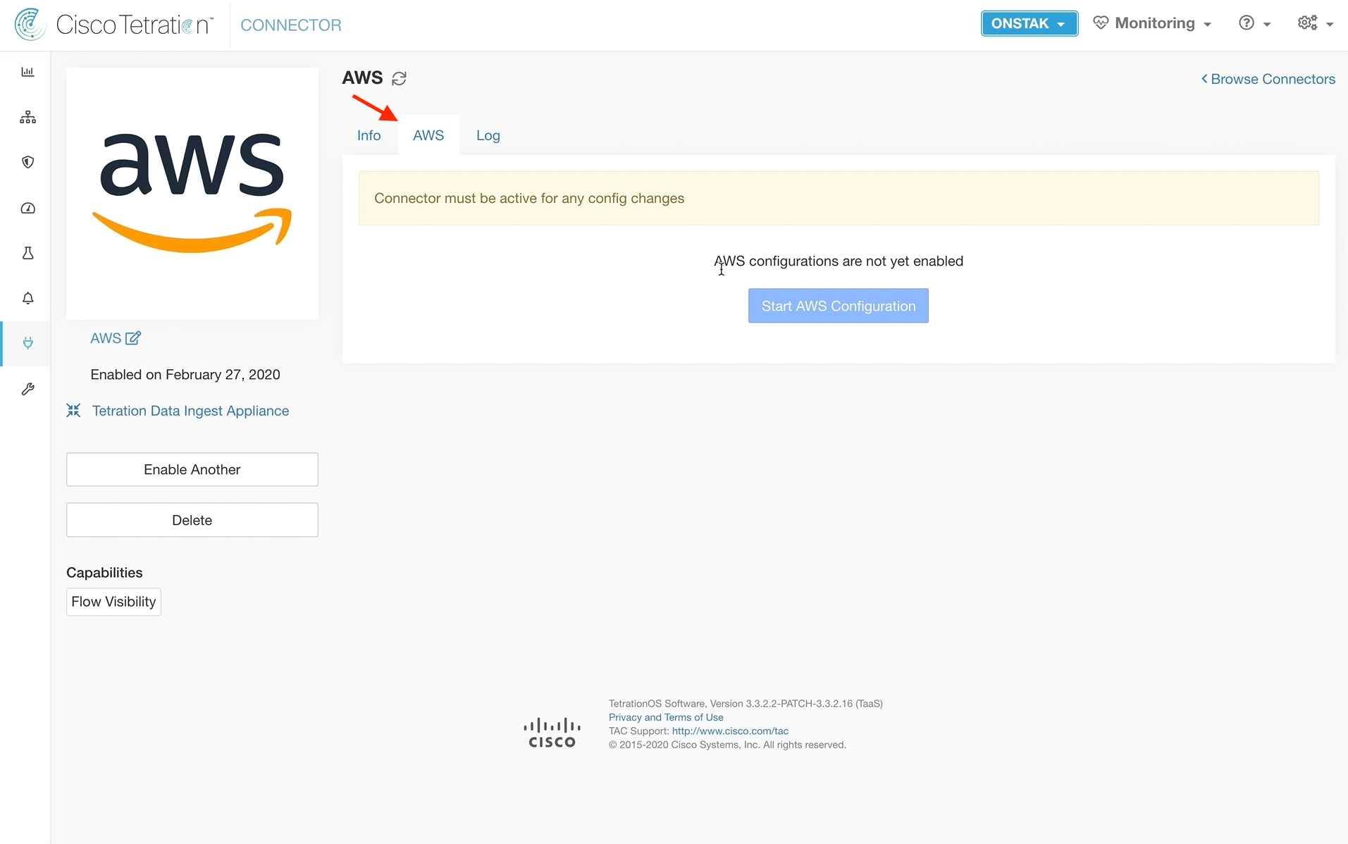
Click on the AWS tab. It takes a few minutes for the connector to become active, so you will likely see the “Connector must be active for any config changes”
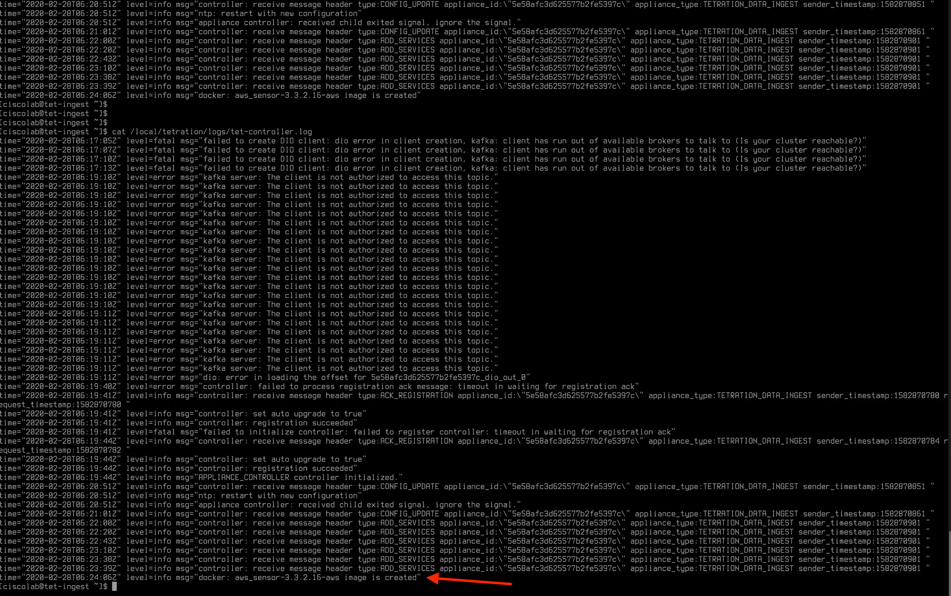
Open a session to the Tetration data ingest appliance and use the command cat /local/tetration/logs/tet-controller.log to view the log files. Once messages are seen that indicate “registration succeeded” and “aws_sensor-3.3.2.16-aws image is created”, the connector should be ready.
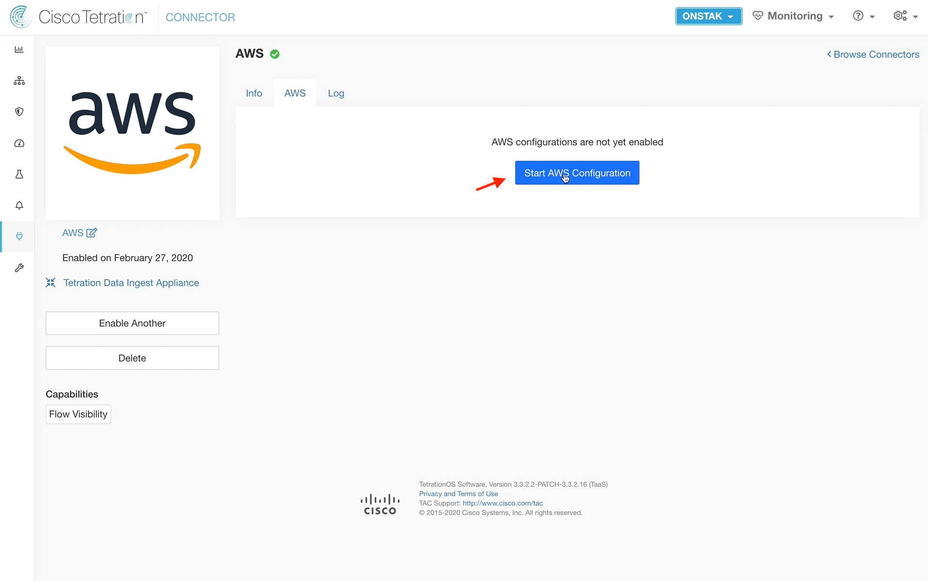
You should now have a green checkmark next to the AWS connector. Click on the AWS connector.
On the AWS tab, select Start AWS Configuration.
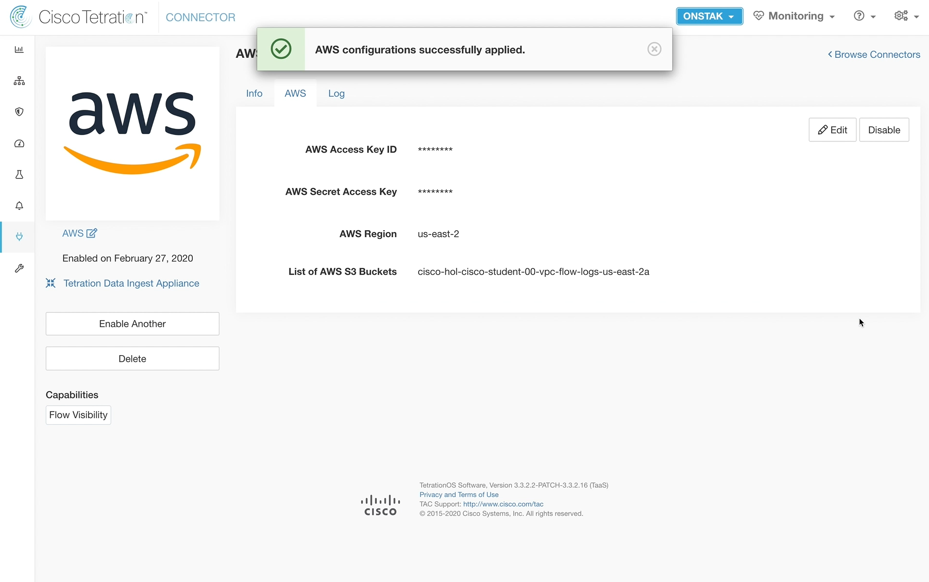
Enter in the AWS details as provided in your student spreadsheet.
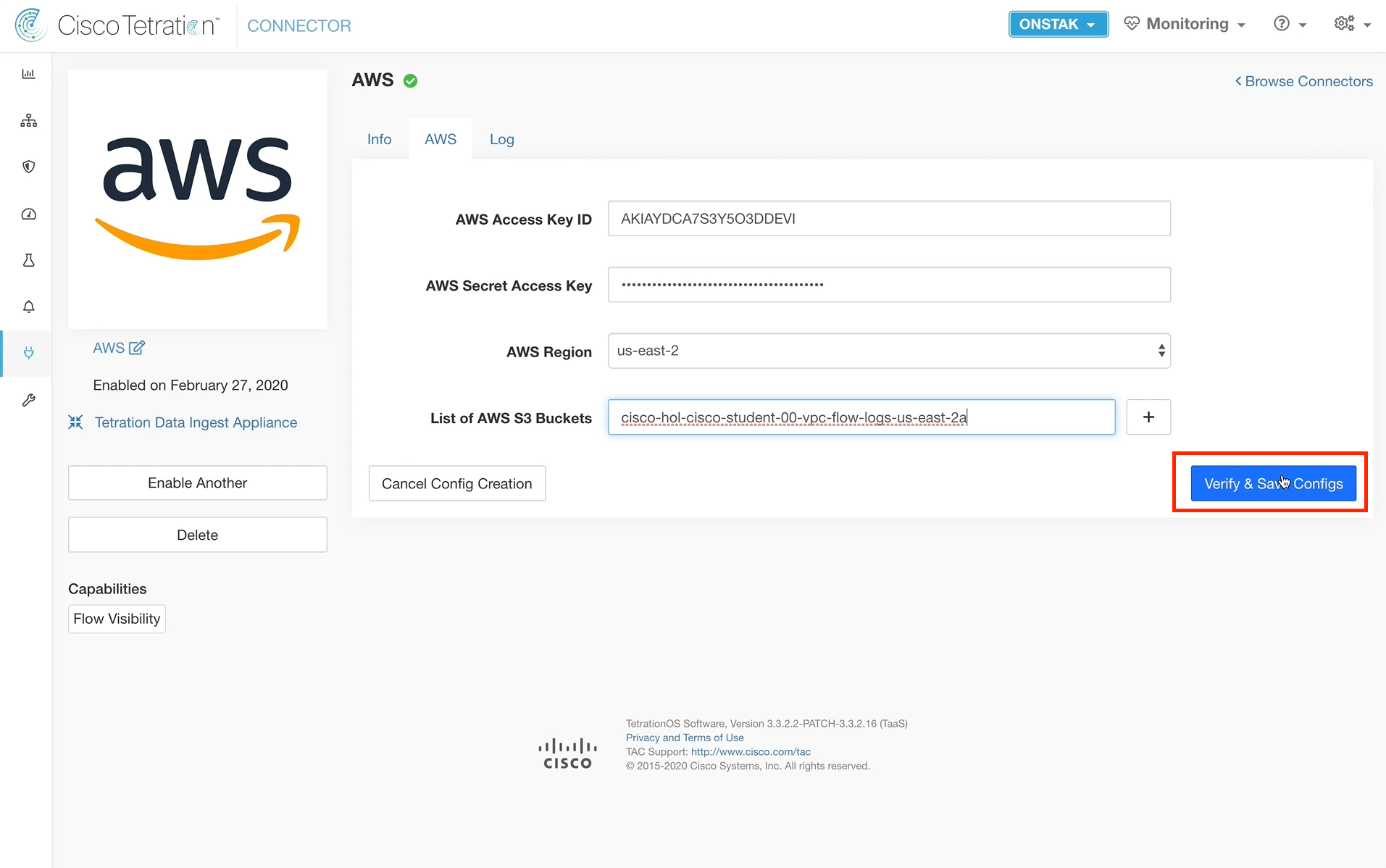
A message should be received “AWS configurations successfully applied”
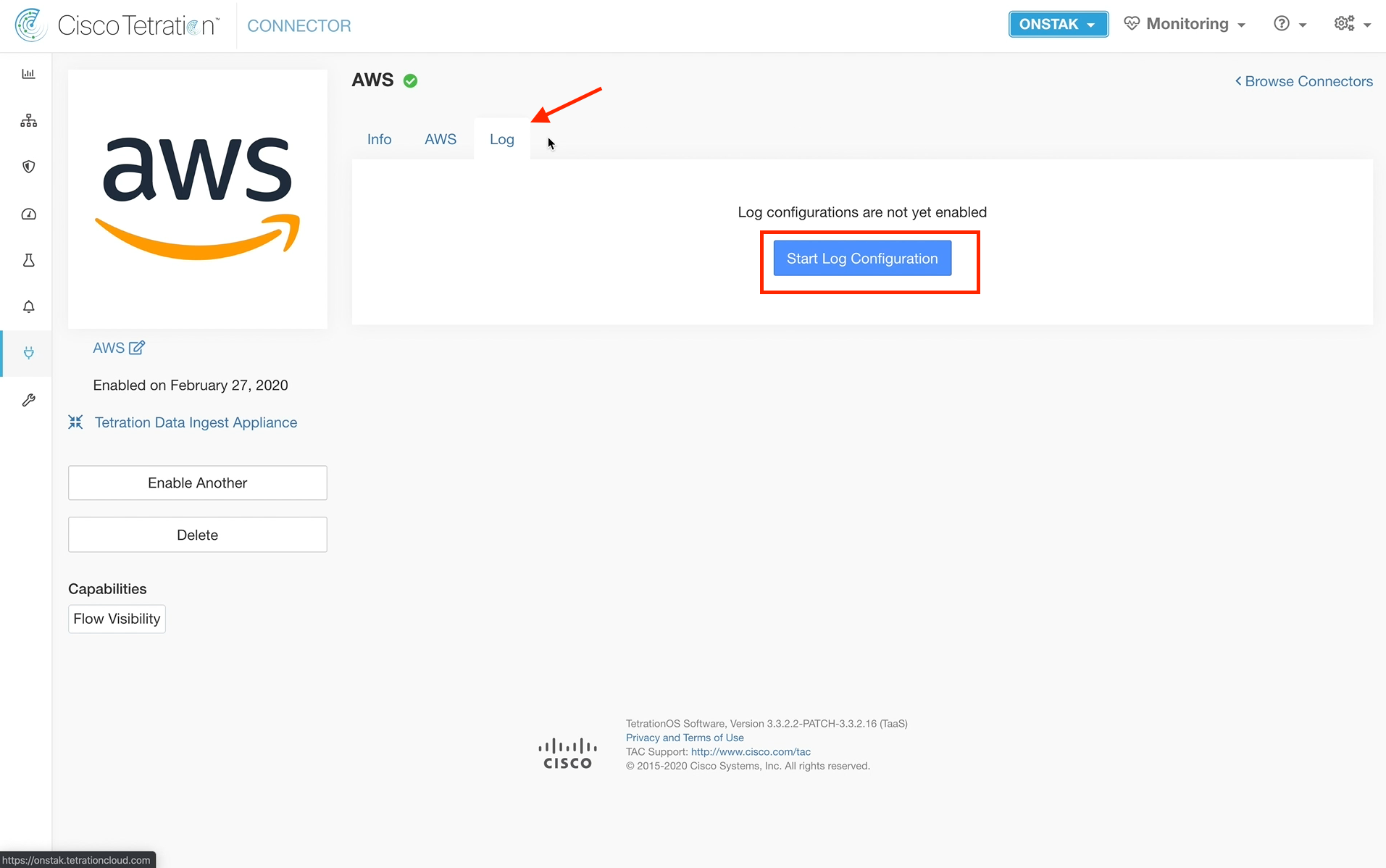
Click on the Log tab and select Start Log Configuration.
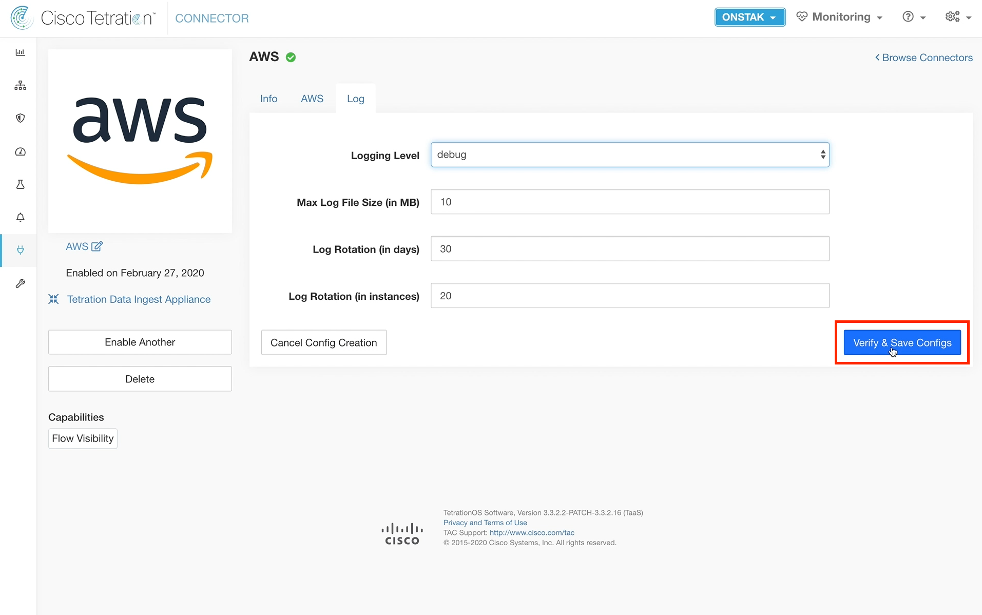
Change the Logging Level to debug and click Verify & Save Configs.
ASA Connector and NAT Stitching
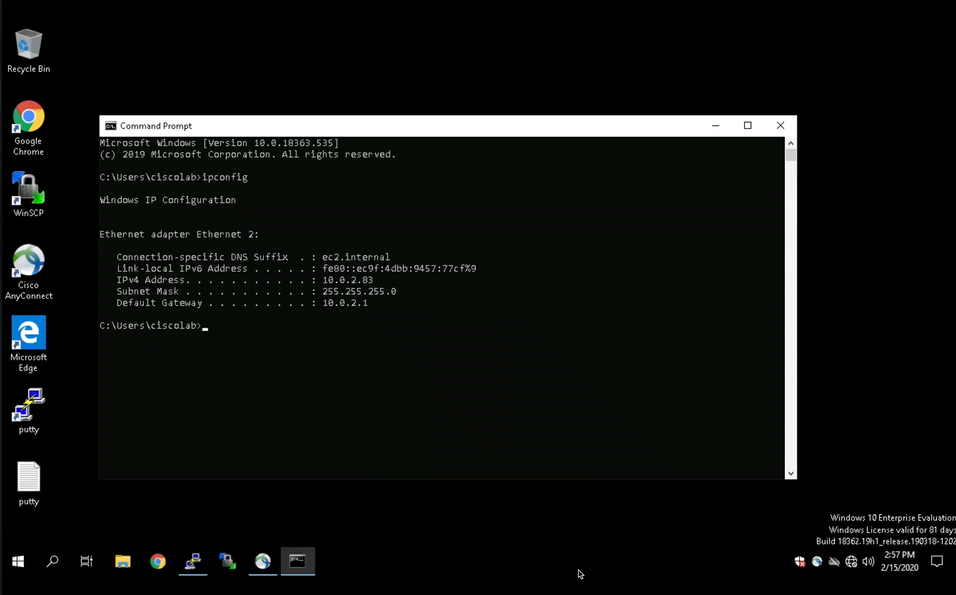
Open a session to the employee desktop machine, open a terminal session and enter the command ifconfig to view the IP address.
REPLACE IMAGE WITH UBUNTU!
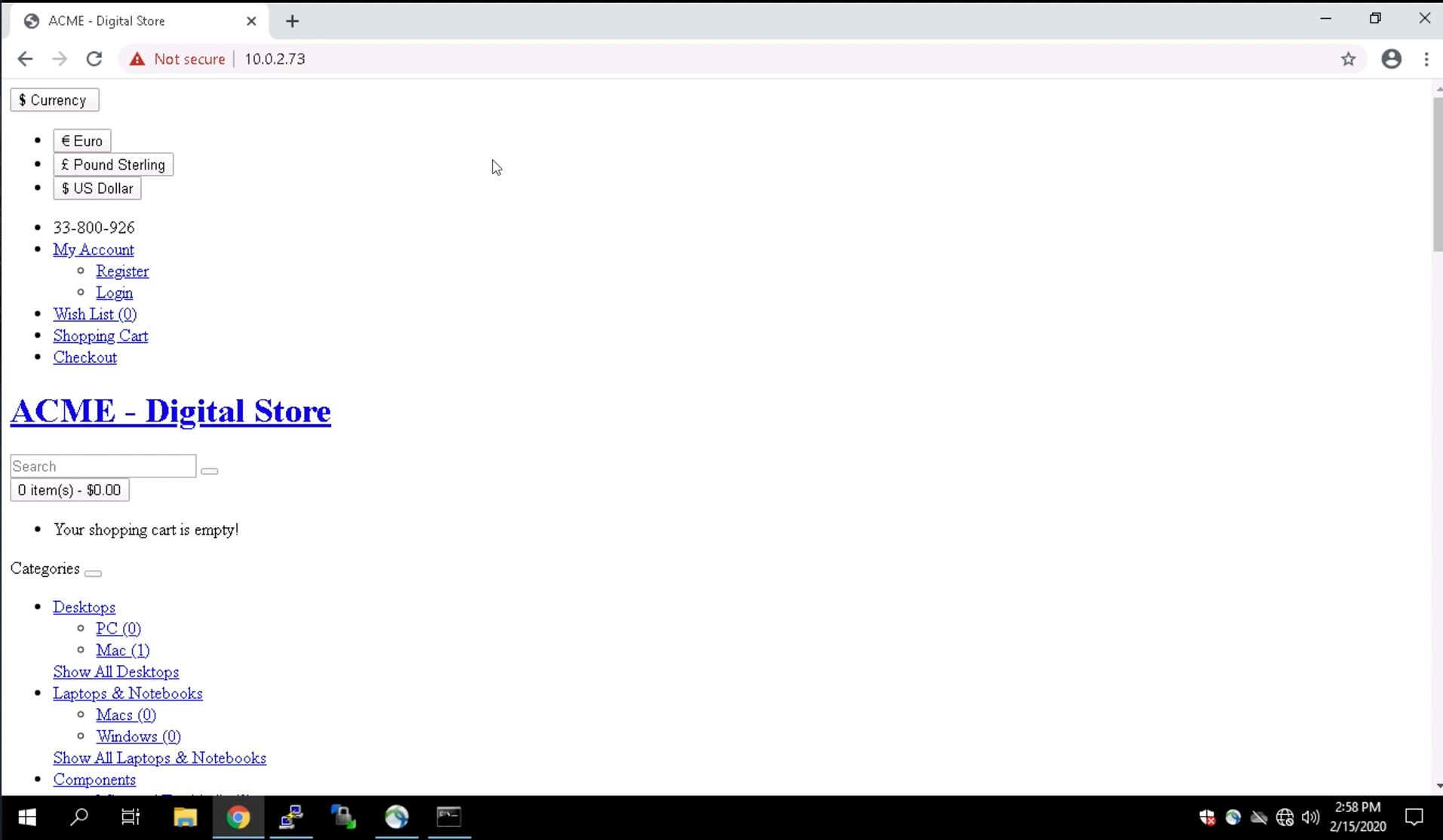
Open a web browser and connect to the OpenCart web server outside NAT address as provided in your student workbook. The outside NAT IP is a static NAT on an ASA firewall that sits between the employee desktop on the outside and the servers on the inside.
REPLACE IMAGE WITH UBUNTU!
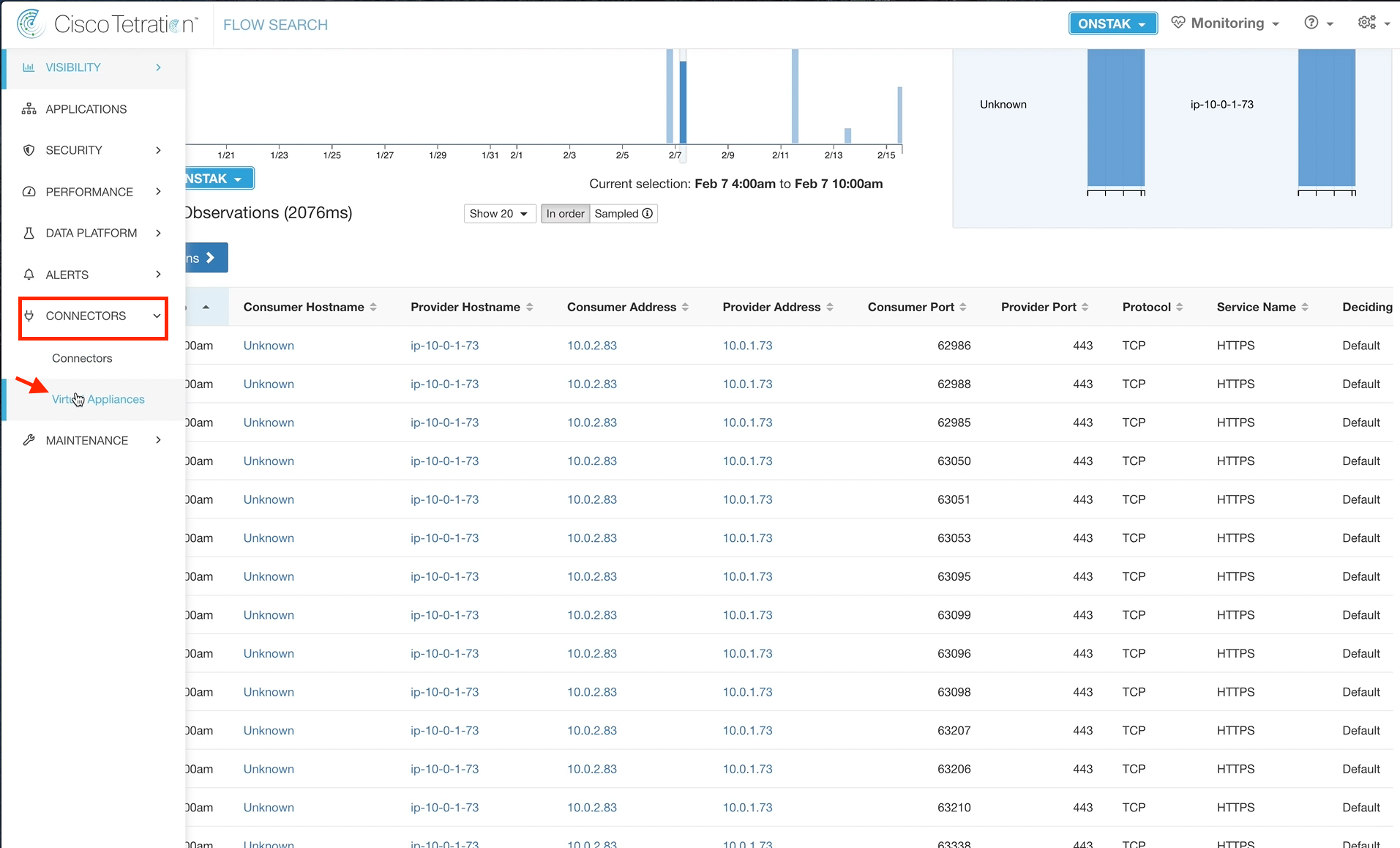
Navigate to Flow Search, and enter the a filter where the Provider is the inside IP address of the Apache web server and the Consumer is the IP address of the employee desktop.
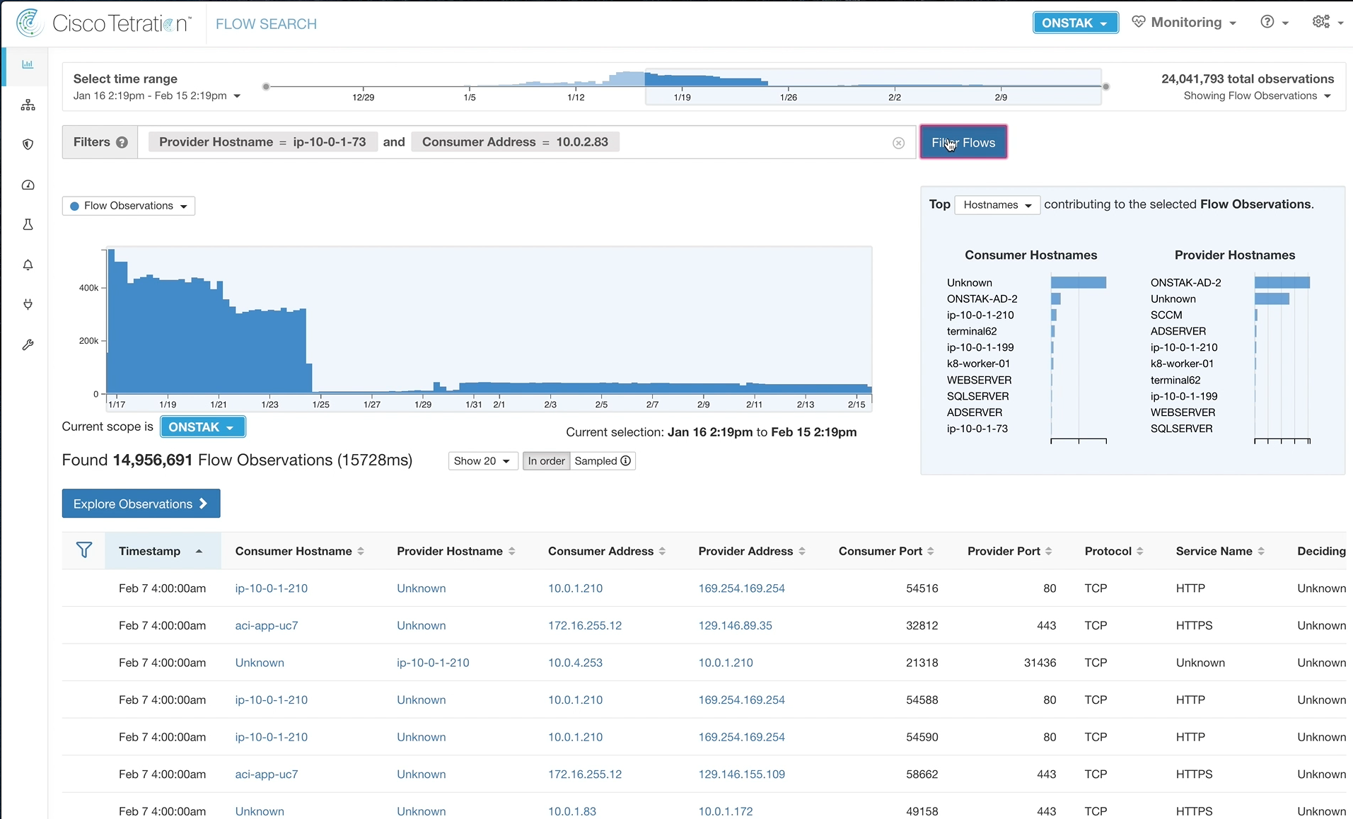
Click on a point in the graph where there is data. You may need to change the time range to display the last hour, and also may need to wait a few minutes for the traffic we just generated to the web server from the employee desktop to show up.

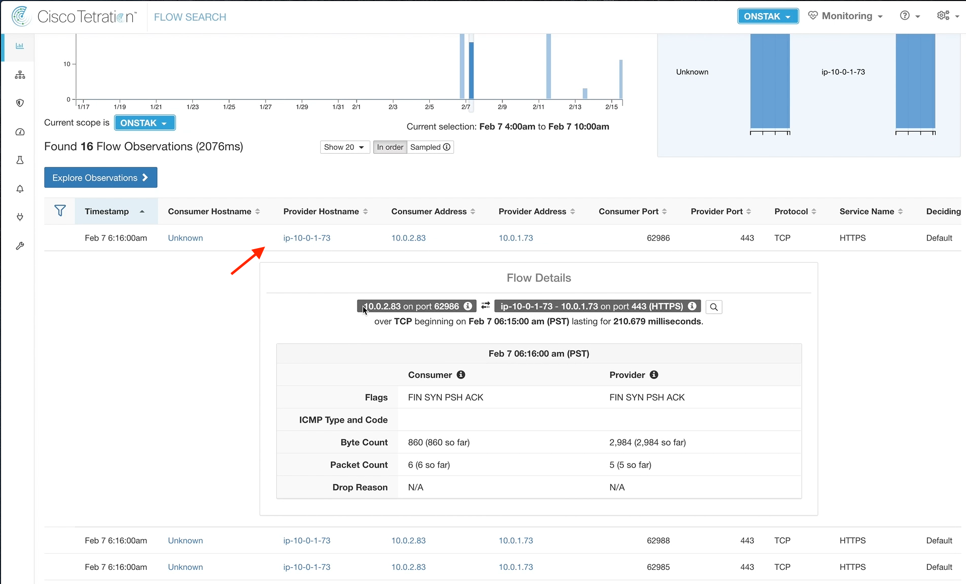
Click on one of the flows to bring up Flow Details. Notice that there is no mention of the outside NAT IP of the Apache web server that we used to connect from the employee desktop.
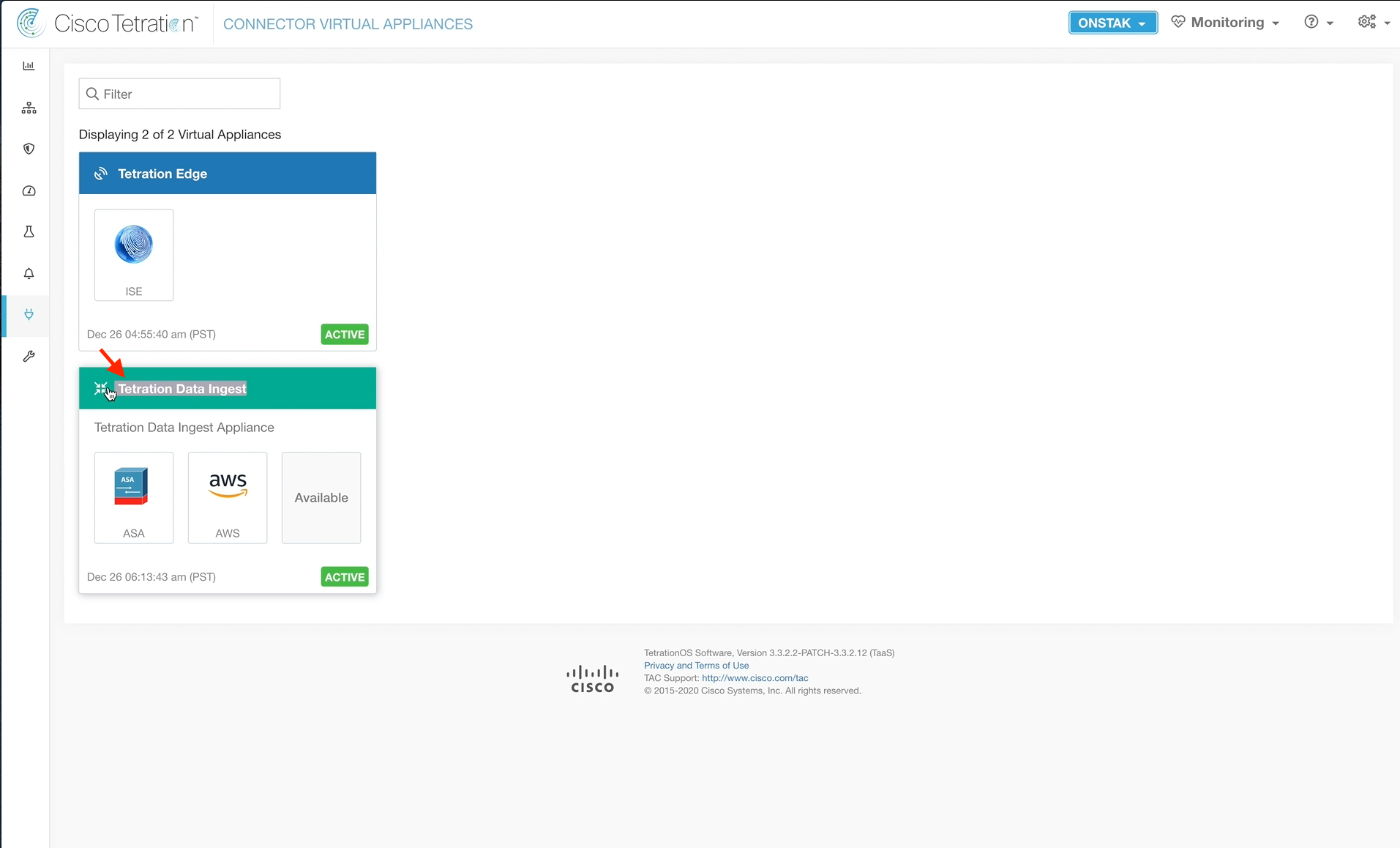
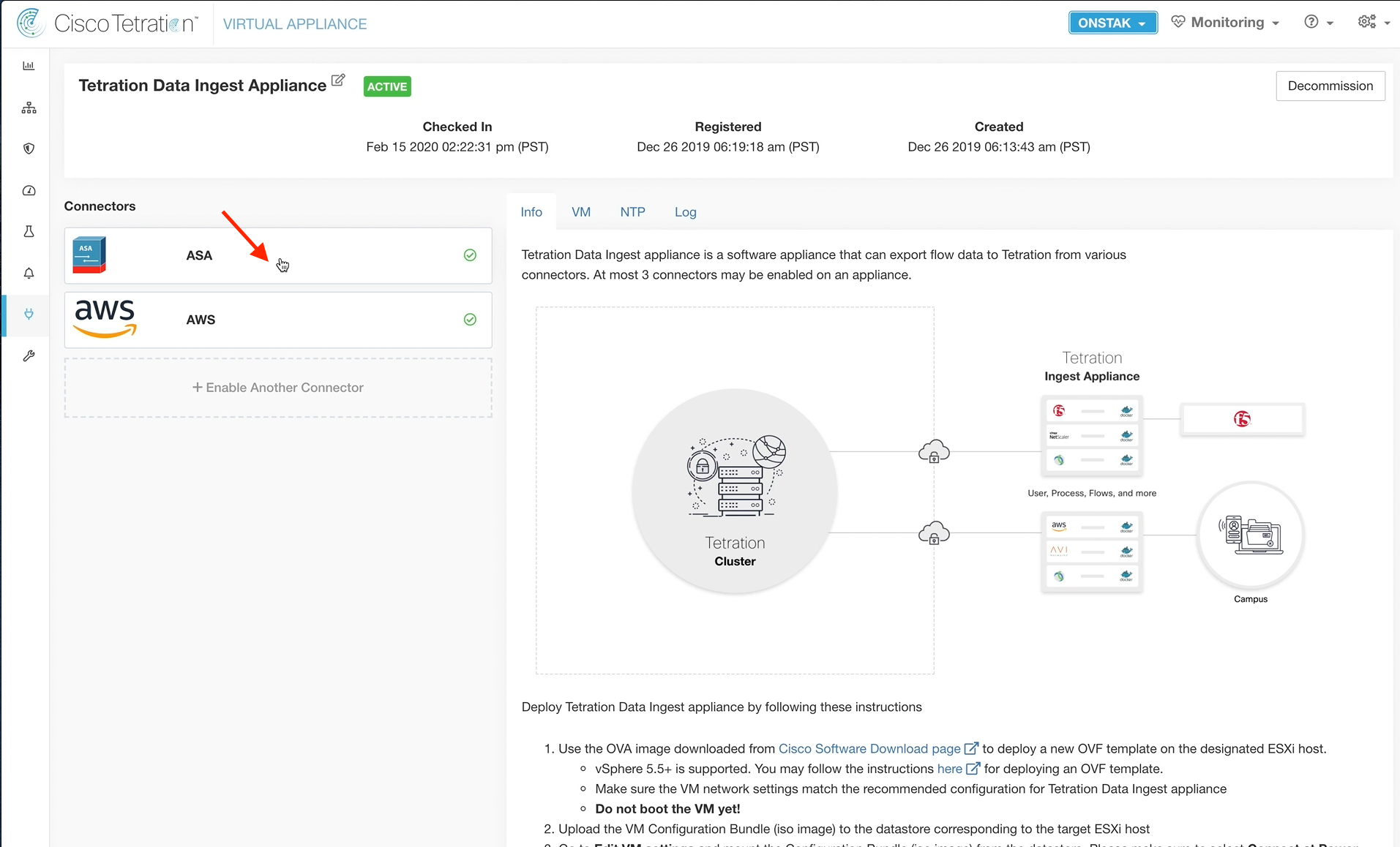
Navigate to Connectors and select Virtual Appliances.
Click on the Tetration Data Ingest heading.
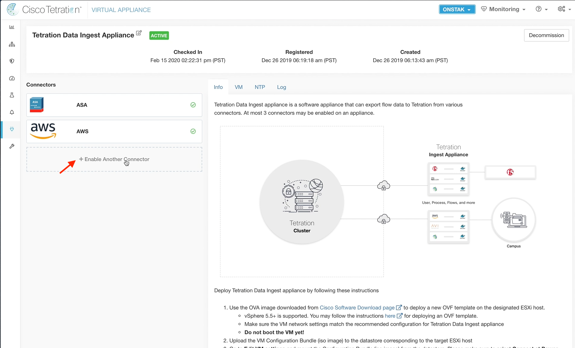
Click Enable Another Connector.
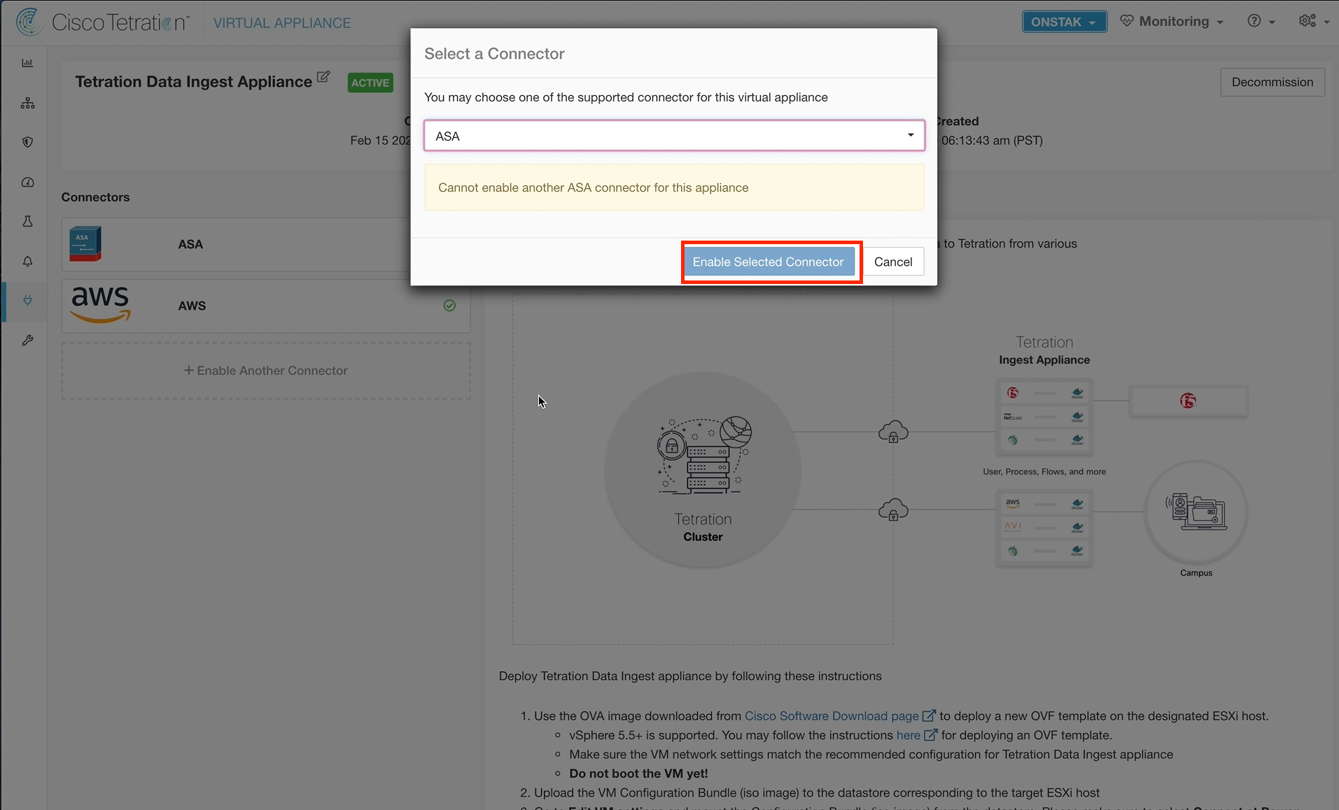
Select ASA from the dropdown and then select Enable Selected Connector.
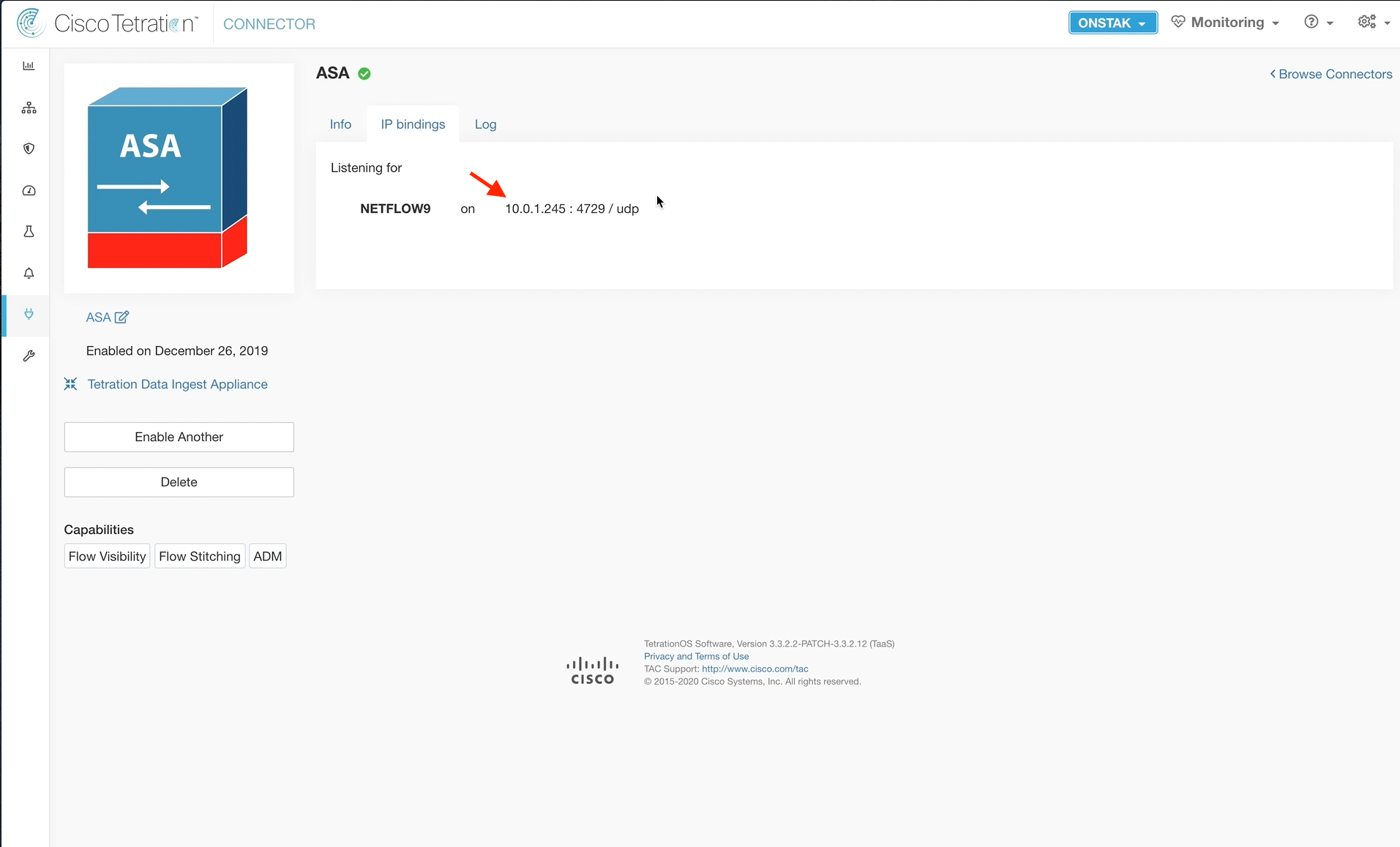
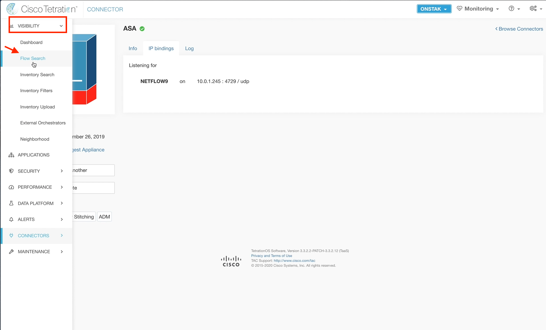
Click on the ASA connector.
It will take a few minutes for the ASA connector to come online. Once it does, an IP bindings tab should become available. Click on the tab to deplay the target IP address and UDP port for Netflow. This is the information that is needed to configure the ASA for Netflow.
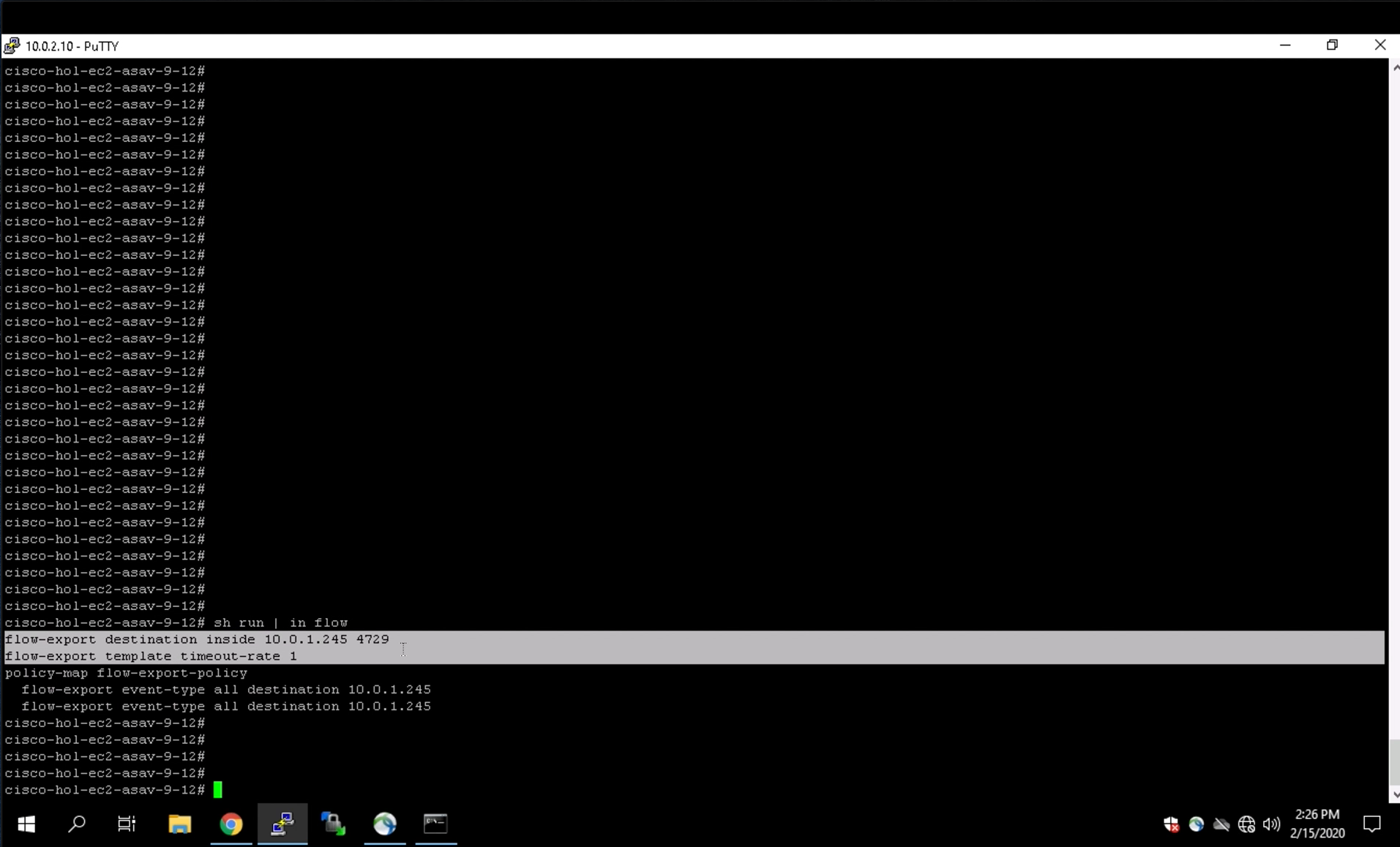
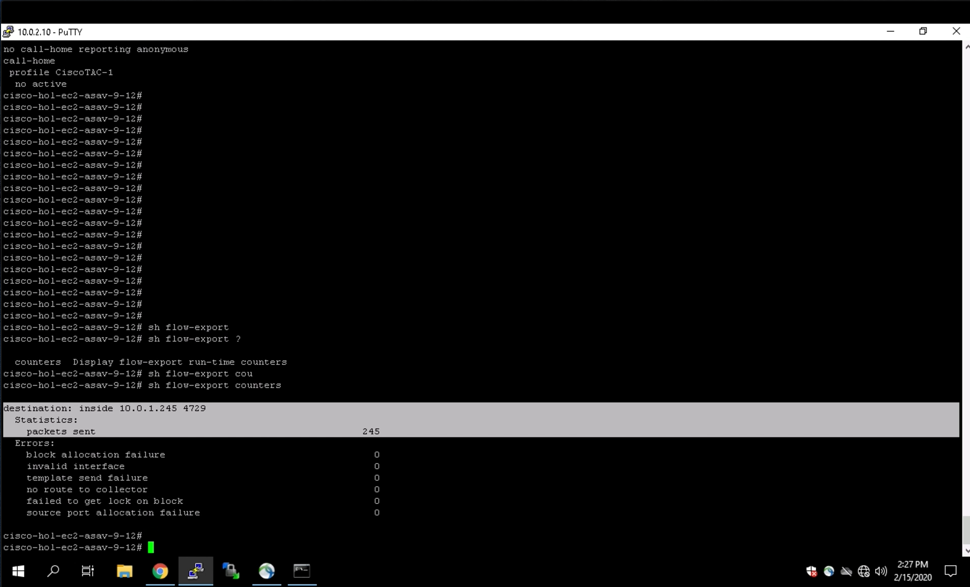
The ASA firewall was configured as part of the lab build process. Open a session to the ASA firewall to view the configuration. Enter the command show run | in flow to view the commands associated with the Netflow configuration.
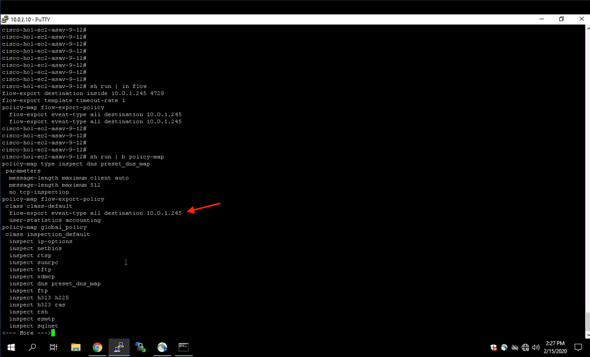
Enter the command show run | g policy-map flow-export to view additional configuration that is needed for Netflow.
Enter the show flow-export counters command to display the Netflow statistics.
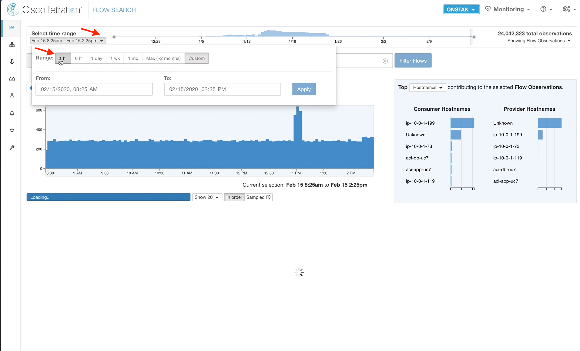
Navigate to Flow Search.
Change the time range to 1 hr.
Create a filter where the Provider Hostname = the hostname of the Apache web server and Consumer Address = the IP of the employee desktop.
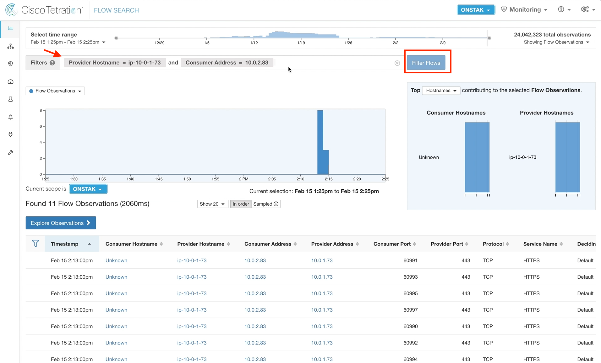
Click on one of the flows returned under Flow Observations. Notice that there is now a field called NAT Direction. Also there is a new link that says “Related Flow”. Click on the Related Flow link.
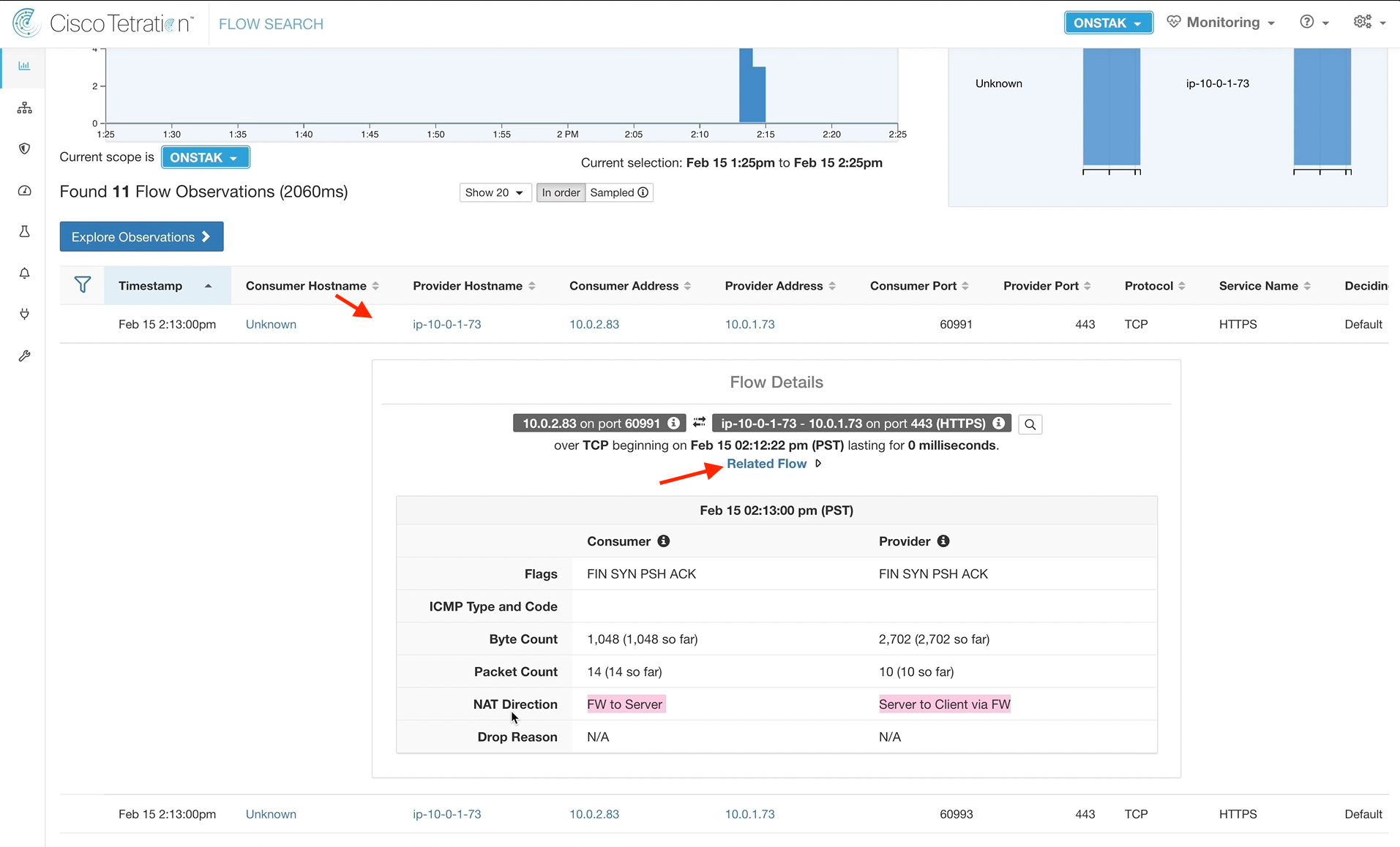
The original flow details are displayed including the outside NAT IP of the Apache web server.

YOU HAVE COMPLETED THIS MODULE
| Return to Table of Contents | Go to Top of the Page | Continue to the Next Module |